Solution - PIERRE Smart Intercom
Description
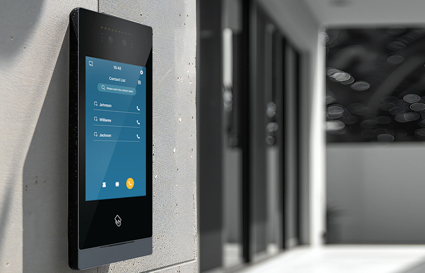
The PIERRE Intercom solution integrates visitor communication and door access directly into the PIERRE system.
The system combines PIERRE Outdoor Intercoms, indoor PIERRE Displays, controlled doors or gates, and the Smart PIERRE application into a single solution.
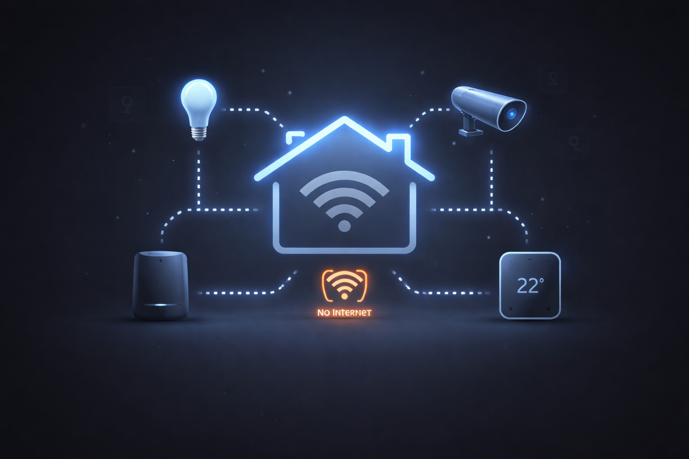
PIERRE Intercoms use SIP-based communication. Communication between devices can operate over the local network without an active internet connection. When internet access is available, users can also receive intercom calls, communicate with visitors, and remotely unlock the corresponding door or gate through the Smart PIERRE application.
System Components
A typical PIERRE Intercom installation can include:
- Outdoor Intercom – installed at the entrance and used by visitors to initiate calls.
- PIERRE Indoor Display – installed inside the property and used to receive calls, communicate with visitors, and unlock the corresponding door or gate.
- Door or Gate – the controlled entrance associated with the Intercom.
- Network Infrastructure – provides local communication between the PIERRE Intercom devices and connectivity to the PIERRE system.
PIERRE Intercom models include:
- Boston
- Springfield
Intercom Functions
Depending on the selected PIERRE Intercom model and project configuration, available functions may include:
- video and audio communication with visitors,
- answering incoming calls from a PIERRE Indoor Display,
- receiving intercom calls through the Smart PIERRE application,
- remote door or gate unlocking,
- visitor snapshots,
- intercom event logging,
- real-time call notifications,
- PIN code access,
- RFID / IC Card access,
- QR code access,
- facial recognition,
- integration with PIERRE Scenes and Automations.
The available functions depend on the selected PIERRE Intercom model and project configuration.
Local and Remote Communication
PIERRE Intercoms are SIP-based and support local communication within the PIERRE system.
Communication between compatible PIERRE devices can take place over the local network without an active internet connection.
An active internet connection is required for remote functions that depend on the Smart PIERRE application, such as receiving and answering intercom calls when the user is outside the local network.
The local network infrastructure must therefore remain operational for local SIP communication.
Indoor PIERRE Display
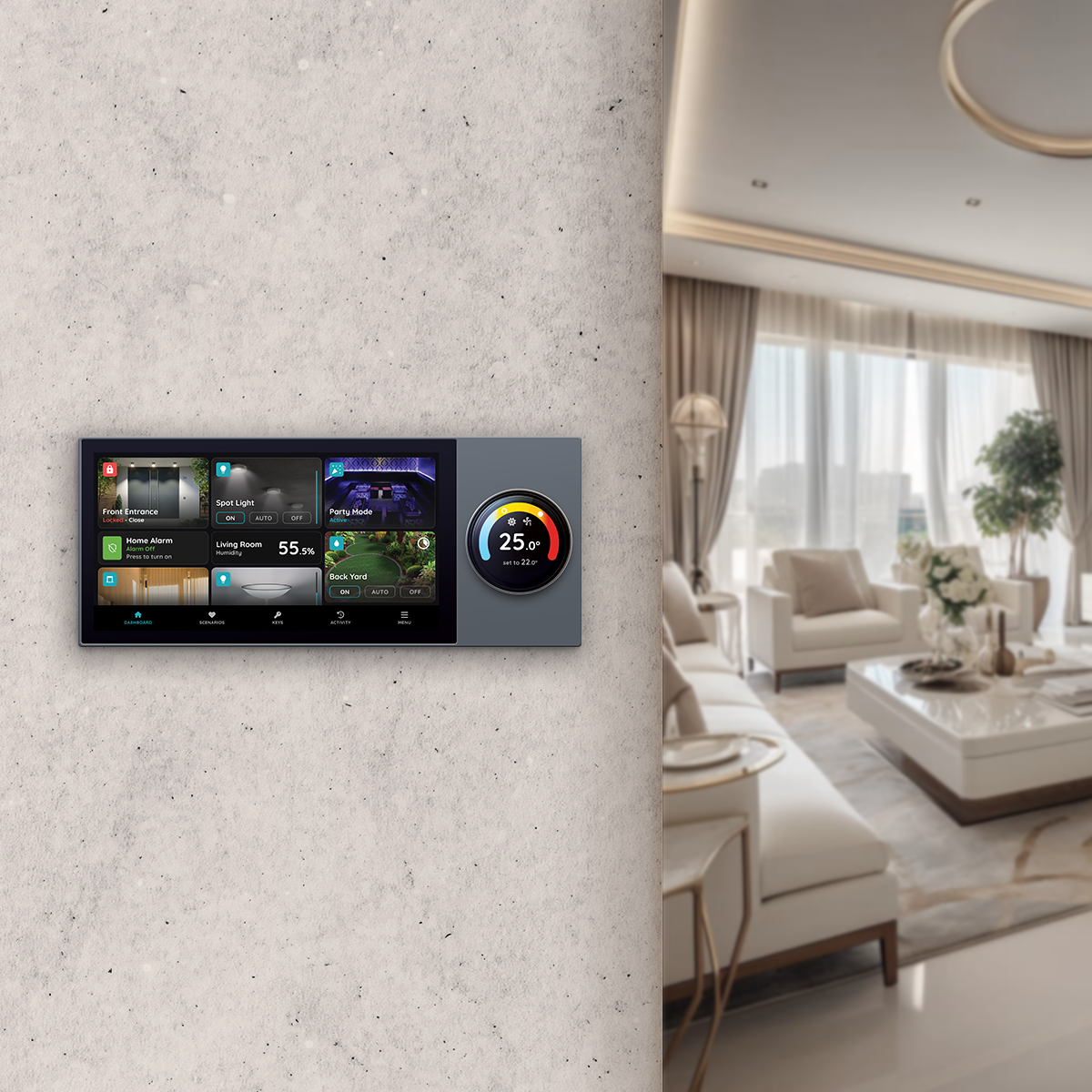
A compatible PIERRE Display can function as the indoor intercom unit.
From the Display, users can:
- receive incoming Intercom calls,
- see the visitor,
- communicate with the visitor,
- unlock the assigned door or gate.
Depending on the Display model, the same device can also provide room control and PIERRE Wave Gateway functionality.
Network Requirements
A network router is a fundamental component of the PIERRE Intercom system.
The network must be planned according to the size and structure of the project, including:
- appropriate IP addressing,
- DHCP configuration,
- fixed IP addresses where required,
- sufficient network capacity for the connected PIERRE Intercoms and Displays.
The network configuration should be planned before commissioning.
Access and Role Configuration
Intercom access within the PIERRE system is managed through Roles.
The Intercom and the corresponding Door must be assigned to the appropriate Role. Users and PIERRE Displays that need access to the Intercom functions must also be assigned the required Role.
For residential projects, a dedicated Intercom Role can be created for this purpose.
The Intercom and associated Door should be assigned to the dedicated Intercom Role and removed from the Default Role where required by the project configuration.
The Intercom Role must then be assigned to the PIERRE Indoor Displays and users who need to receive and answer Intercom calls and access the associated Door.
Setup in PIERRE Partner Application
PIERRE Intercoms are configured in the PIERRE Partner application.
Go to:
Menu → Intercoms → Add
Select the PIERRE Intercom
Select the appropriate PIERRE Intercom from the available devices.
Configure the Intercom Settings
Configure the required settings:
- Name – Enter a name for the Intercom.
- Image – Add an image where applicable for easier identification.
- Role – Select the appropriate Role for the Intercom.
- Doors – Select the Doors that can be unlocked using the Intercom.
Only the Doors intended to be controlled through the Intercom should be assigned.
Save the Configuration
Tap Save to create the Intercom.
After saving, select the newly created Intercom to view or modify its configuration.
Parameters
Open the Parameters tab to view the configuration and communication parameters of the PIERRE Intercom.
The required parameters are automatically generated by the PIERRE system and can be modified where required by the project configuration.
Technical Notes
- Plan the location of the Outdoor Intercom before the entrance or facade is completed.
- Check the mounting height and camera angle so visitors are positioned correctly within the camera view.
- Indoor Displays should be positioned so they are easily accessible when an incoming call is received.
- If the Display also functions as a PIERRE Wave Gateway, its location should also provide suitable wireless coverage.
- Local SIP communication requires the local network infrastructure to remain operational.
- Remote Smart PIERRE Intercom functions require an active internet connection.
- Access to Doors and Intercom functions must be configured through the appropriate Roles.
- Available access methods and Intercom functions depend on the selected PIERRE Intercom model and project configuration.
- The diameter of the power cable must be increased according to the distance
- We also recommend installing a UPS power supply for the Pierre controller and the intercom too
Key Features
Remote Communication and Door Unlocking
Answer intercom calls remotely using the PIERRE app. When a visitor rings the doorbell, users can communicate with them and unlock the door from anywhere.
Visitor Snapshot and Event Logging
When the doorbell is pressed, the intercom automatically captures a snapshot of the visitor. The image is stored in the PIERRE system together with the event log, allowing users to review visitor activity.
Multiple Unlocking Methods
The intercom supports multiple access methods, including facial recognition, QR codes, PIN codes, and IC cards, providing flexible and secure access control.
Facial Recognition
Advanced facial recognition technology enables convenient, touch-free access for authorized users.
SIP-Based Communication
The intercom uses the SIP protocol to communicate with other devices and systems within the PIERRE ecosystem, such as indoor displays, guard stations, and management centers.
Real-Time Notifications
Users receive real-time notifications when someone rings the intercom. All events are recorded in the PIERRE app for later review.
Designed for Outdoor Use
The outdoor unit features infrared night vision, high-brightness LED illumination, and a weather-resistant design for reliable operation in various environmental conditions.
The PIERRE Intercom solution combines security, convenience, and smart home integration for residential and commercial installations.
PIERRE INTERCOMS
The PIERRE Intercoms are SIP-based and operate on an offline-first principle. This means that communication is established over the local network whenever possible. If an internet connection is available, remote communication through the PIERRE app is also supported. As the system is SIP-based, local communication does not depend on a cloud connection.
A network router is a fundamental component of the PIERRE door entry system. The modem/router provided by the internet service provider is suitable for this purpose.
The router must be configured with an appropriate DHCP server IP range, depending on the size of the project.
Example
For a residential building with 50 apartments:
Router IP address: 192.168.1.100
Reserved IP addresses for the indoor units:
- Apartment 1:
192.168.1.1 - Apartment 6:
192.168.1.6 - Apartment 50:
192.168.1.50
DHCP server IP range:192.168.1.101 – 192.168.1.254
Role setup for PIERRE intercoms for residential building
The PIERRE intercom must be added to the Common Controller using a separate role.
Each apartment must have access to the intercom and the corresponding door for remote unlocking. The intercom and the associated door must be assigned to a dedicated role named Intercom and removed from the Default role.
The Intercom role must then be assigned to the PIERRE indoor displays (intercom indoor units) and to the users who should be able to receive and answer intercom calls.
PIERRE BOSTON Setup
Every PIERRE Display Requires a Fixed IP Address
For reliable operation and optimal performance, every PIERRE display must be assigned a fixed IP address. This ensures stable communication and helps prevent IP address conflicts within the network.
Setup in PIERRE Partner Application
Menu → Intercoms → Add
Select the PIERRE Intercom
Choose the PIERRE Intercom from the list of available devices.
Configure the Intercom Settings
-
Name: Enter a name for the intercom.
-
Role: Select the appropriate role for the intercom.
-
Doors: Select the doors that can be unlocked using the intercom.
Save the Configuration
Click Save to create the intercom. After saving, select the newly created intercom to view or modify its settings.
Access Parameters
Open the Parameters tab to view the configuration settings for the PIERRE Intercom. These parameters are automatically generated by the system and can be modified if required.
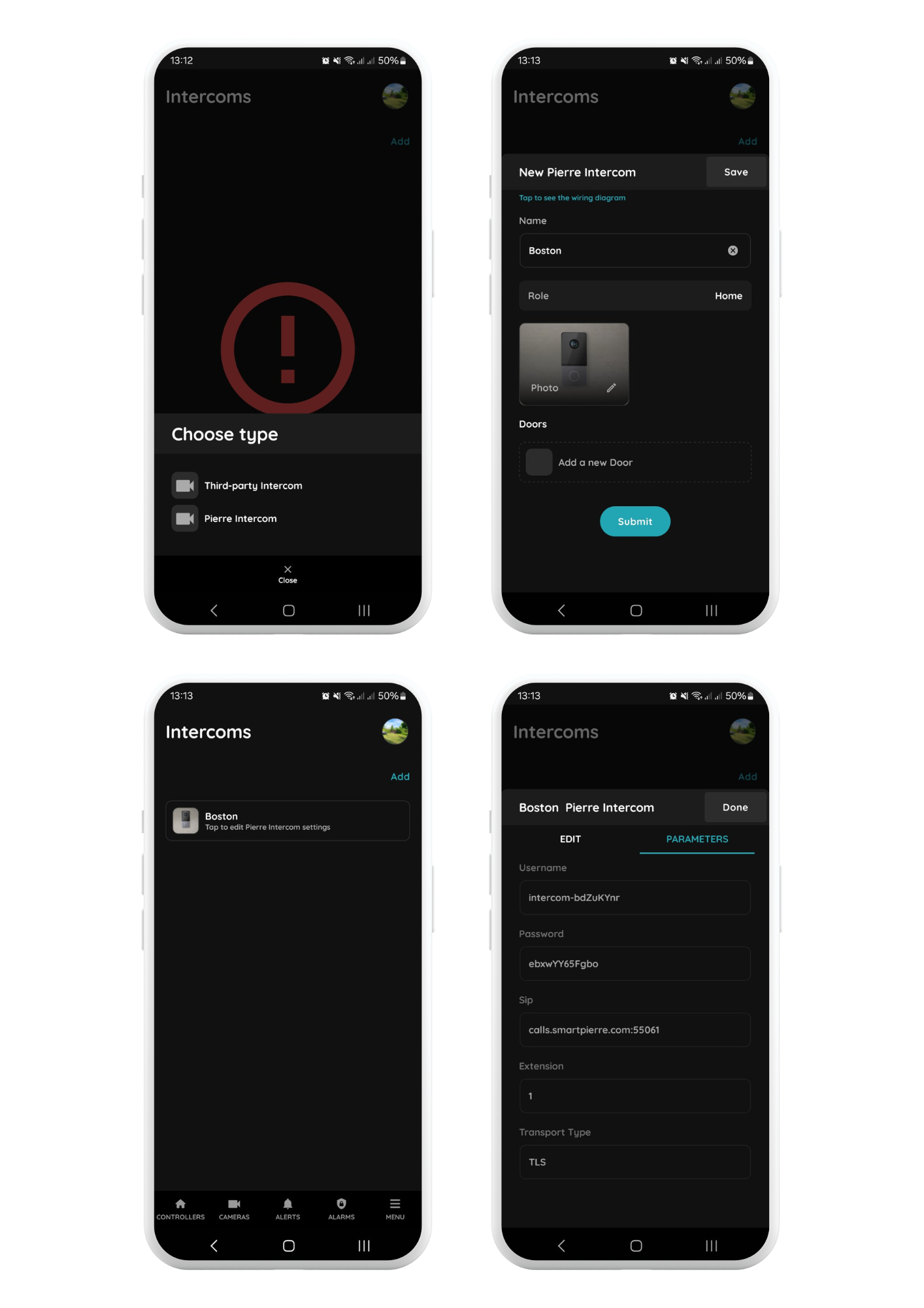
The following parameters are automatically generated and must be configured in the PIERRE intercom:
- Username: Enter the Username generated in the PIERRE Partner application.
- Password: Enter the Password generated in the PIERRE Partner application.
- SIP: Enter the SIP server parameters provided by the PIERRE Partner application.
- Extension: Enter the automatically generated Extension value from the PIERRE Partner application (e.g. 1). If multiple intercoms are added to the system, this value is automatically incremented for each additional intercom.
- Transport Type: Set to TLS.
Setup the PIERRE Boston Intercom:
1. Settings
- Click on the Settings icon.
- The default password is 801801.
Important: Change the default password after completing the setup and store it securely for future reference.
2. Call Settings
- Open Call Settings, then navigate to SIP Account Settings.
3. SIP Account Configuration
- Username: Replace the default value with the automatically generated Extension value from the PIERRE Partner application (e.g. 1).
- Local SIP Account: This value is automatically generated by the system and should not be modified.
Format:sip:1@ip-address:5060
SIP Account 1
- Remark: Enter a name for the intercom.
- Username: Enter the Username generated in the PIERRE Partner application.
- Server Password: Enter the Password generated in the PIERRE Partner application.
- Server Address:
calls.smartpierre.com - Server Port:
55061 - Transfer Method: Set to TLS (Transport Layer Security) to ensure compatibility with the Yettel network and other providers using Double NAT.
4. Save and Verify Connection
-
Save the settings and exit the menu.
-
Reopen SIP Account Settings to verify the connection status. The status should display Connected.
-
This confirms that the intercom has been configured correctly and is ready for operation.
Configuring the Call Recipients on the Door Intercom
Step 1: Access the Intercom Settings
- Open Settings on the intercom.
- Enter the default password: 801801.
Step 2: Navigate to Call Settings
- Open Call Settings.
- Enable Resident List Call.
- Open Contact List Management.
- Select Add To, then Add Contacts.
Step 3: Add a New Contact
- Remark: Enter a descriptive name, for example:
- Apartment 1 - John Doe
- SIP Account: Enter the SIP address in the following format:
- sip:1@192.168.1.1 where 192.168.1.1 is the fixed IP address of the corresponding PIERRE indoor display.
- Click Save to store the contact.
Example:
For Apartment 13, if the PIERRE display has the IP address 192.168.1.13, the SIP account should be:
sip:1@192.168.1.13
The recommended router configuration is:
- Router IP address:
192.168.1.100 - DHCP server range:
192.168.1.101 – 192.168.1.250
The sip:1@ prefix identifies Intercom 1 in the building.
If multiple PIERRE intercoms are installed, each intercom uses its own SIP identifier. For example:
- Intercom 1:
sip:1@... - Intercom 2:
sip:2@...
Step 4: Test the Call
- After adding the contact, place a test call to verify that the connection has been configured correctly and that two-way communication is working.
Assigning Fixed IP Addresses to Displays
Step 1: Access Network Settings
- On the display, pull down the status bar from the top of the screen.
- Connect the PIERRE display to the internet using a Wi-Fi network (this is optional and not required for door intercom functionality).
- Use Ethernet for internal network communication of the intercom system.
Step 2: Configure Ethernet for Internal Communication
- Use Ethernet for internal network communication with the intercom system.
- Check Primary network. There are two ways to configure this:
- If the displays only have LAN access, it is essential to enable the Primary Network in the display’s Ethernet settings.
- Alternatively, if the apartment has its own internet access via a Wi-Fi network, and the Ethernet connection is used for the intercom on the display, then the Wi-Fi network must be set as the Primary Network in the Wi-Fi settings.
- Navigate to IP Settings and select Static.
Step 3: Assign Fixed IP Address
- IP Address:
- Assign a fixed IP address that is outside of the DHCP range to avoid conflicts.
- Gateway:
- Enter the IP address of the network gateway (typically the router’s IP address).
- Subnet Mask:
- Configure the appropriate subnet mask (e.g., 255.255.255.0 for most networks).
- DNS:
- Set the domain name server (DNS) as required by the network.
Step 4: Router Configuration
- Ensure the router manages IP distribution for all devices on the network.
- The display’s IP address must remain outside the DHCP range.
Example Configuration for Smaller Projects (Up to 45 Apartments):
- Router DHCP Server Start Address
Configure the DHCP server to start assigning IP addresses from 192.168.1.100 (or another suitable address).
- Static IP Addresses for PIERRE Displays
Assign a fixed IP address to each PIERRE display below the DHCP range. For example:
- Apartment 1:
192.168.1.1 - Apartment 6:
192.168.1.6 - Apartment 45:
192.168.1.45
This configuration reserves the lower IP address range for PIERRE displays while allowing the DHCP server to assign addresses to other network devices, helping to prevent IP address conflicts.
PIERRE SPRINGFIELD Setup
Every PIERRE Display Requires a Fixed IP Address
For reliable operation and optimal performance, every PIERRE display must be assigned a fixed IP address. This ensures stable communication and helps prevent IP address conflicts within the network.
Setup in PIERRE Partner Application
Menu - Intercoms - Add
Select the PIERRE Intercom
Choose the PIERRE Intercom from the available options.
Configure the Intercom Settings
- Name: Enter a custom name of your choice.
- Role: Select the appropriate role for the intercom.
- Doors: Specify which doors can be opened by the intercom.
Save the Configuration
After saving, click on the newly created intercom to view or modify settings.
Access Parameters
Navigate to the Parameters tab to find the configuration settings for the PIERRE Intercom. These settings are automatically generated by the system and can be adjusted as needed.
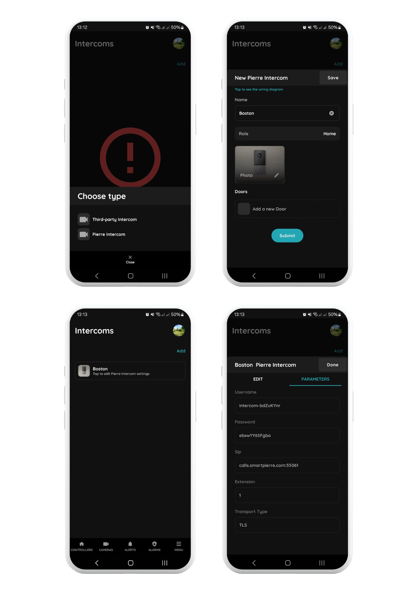
Setup the PIERRE Springfield Intercom:
- Default Network Configuration: DHCP
By default, the PIERRE Springfield intercom obtains its IP address from the DHCP server (managed by your router). - Connect to the Network
- Connect to the network by Wi-Fi or Ethernet with your notebook or computer.
- Scan the network using an IP scanner (e.g., Angry IP Scanner) to identify the intercom’s assigned IP address.
- Access the Intercom’s Web Interface
- Open a web browser and enter the identified IP address.
- Default login credentials:
- Username: admin
- Password: admin
- Important: Change the default login credentials at the end of the setup process and record the new details securely.
Configuring SIP Account Settings
In the intercom’s web interface, set up the following parameters under SIP Account Settings:
- Username: Enter the extension from the PIERRE Partner application.
- User Name 1: Enter the username from the PIERRE Partner application.
- Server Password: Enter the password from the PIERRE Partner application.
- Server Address: Input the server address provided by PIERRE Partner application.
- Server Port: Set to 55061.
- Transfer Mode: Select TLS (Transport Layer Security).
Configuring Contact Settings
- Navigate to Address Book under Contact Settings.
- Add a contact:
- Remark: Provide a name (e.g., Apartment 1, John Doe).
- SIP: Enter the SIP address in this format:
sip:1@display-ip-address
Call Settings
- Configure the Call Behavior:
- Short Press: Assign the contact from the address book to the button’s short press.
- Long Press: Assign the same contact for the long press.
- Save the settings and test the functionality to ensure the intercom calls the intended recipient when the button is pressed.
Assigning Fixed IP Addresses to Displays
Step 1: Access Network Settings
- On the display, pull down the status bar from the top of the screen.
- Connect the PIERRE display to the internet using a Wi-Fi network (this is optional and not required for door intercom functionality).
- Use Ethernet for internal network communication of the intercom system.
Step 2: Configure Ethernet for Internal Communication
- Use Ethernet for internal network communication with the intercom system.
- Check Primary network. There are two ways to configure this:
- If the displays only have LAN access, it is essential to enable the Primary Network in the display’s Ethernet settings.
- Alternatively, if the apartment has its own internet access via a Wi-Fi network, and the Ethernet connection is used for the intercom on the display, then the Wi-Fi network must be set as the Primary Network in the Wi-Fi settings.
- Navigate to IP Settings and select Static.
Step 3: Assign Fixed IP Address
- IP Address:
- Assign a fixed IP address that is outside of the DHCP range to avoid conflicts.
- Gateway:
- Enter the IP address of the network gateway (typically the router’s IP address).
- Subnet Mask:
- Configure the appropriate subnet mask (e.g., 255.255.255.0 for most networks).
- DNS:
- Set the domain name server (DNS) as required by the network.
Step 4: Router Configuration
- Ensure the router manages IP distribution for all devices on the network.
- The display’s IP address must remain outside the DHCP range.
Example Configuration for Smaller Projects (Up to 45 Apartments):
- Router DHCP Server Start Address:
Set the DHCP server to start distributing IP addresses from, e.g., 192.168.1.100. - Static IP Range for Displays:
Assign static IPs below the DHCP range, e.g.:- Display for Apartment 1: 192.168.1.1
- Display for Apartment 6: 192.168.1.6
- Display for Apartment 45: 192.168.1.45
By following these steps, the intercom system will function seamlessly, avoiding IP conflicts and ensuring reliable communication across the network.
Schemes - Only Pierre controller opens the door
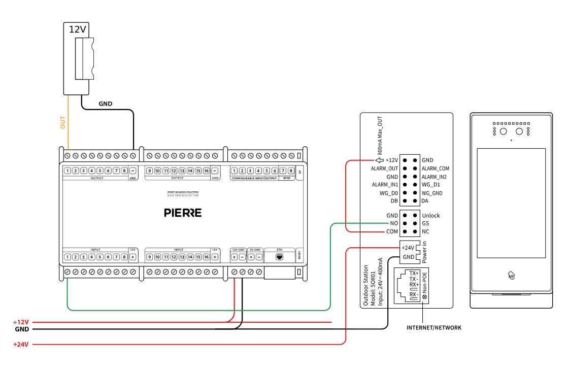
Only Pierre controller opens the door (Boston opens via Pierre controller)
Cables - Only Pierre controller opens the door
| Position | Wires | Diameter | Type | Comment |
|---|---|---|---|---|
| From Power Supply to Boston Intercom | 2 | 1 mm² | H07V-K | +24, GND |
| From Pierre to Boston Intercom | 2 | 0.5 mm² | H07V-K | +12V, SIGNAL |
| From Pierre to Lock | 2 | 1 mm² | H07V-K | OUT, GND |
| From Network switch to Boston Intercom | 4 | 0.25 mm² | Cat5 UTP | LAN (RX+, RX-, TX+, TX-) |
Schemes - Only Boston opens the door
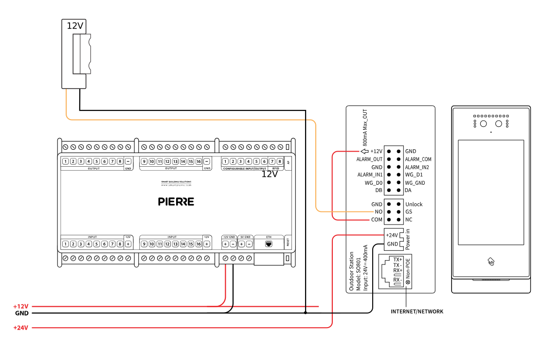
Only Boston opens the door
Cables - Only Boston opens the door
| position | wires | diameter | type | comment |
|---|---|---|---|---|
| From Power Supply to Boston Intercom | 2 | 1 mm² | H07V-K | +24V, GND |
| From Boston Intercom to Lock | 2 | 1 mm² | H07V-K | +12V, GND |
| From Network switch to Boston Intercom | 4 | 0.25 mm² | Cat5 UTP | LAN (RX+, RX-, TX+, TX-) |
Schemes - Hybrid (Boston and Controller opens the door too)
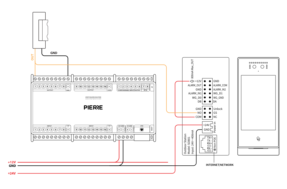
Pierre controller and Boston opens the door too
Cables - Hybrid (Boston and Controller opens the door too)
| position | wires | diameter | type | comment |
|---|---|---|---|---|
| From Electric box to Boston Intercom | 2 | 1 mm² | H07V-K | +24V, GND |
| From Pierre to Lock | 2 | 1 mm² | H07V-K | OUT, GND |
| From Boston Intercom to Lock | 2 | 1 mm² | H07V-K | OUT, GND |
| From Network switch to Boston Intercom | 4 | 0.25 mm² | Cat5 UTP | LAN (RX+, RX-, TX+, TX-) |
Schemes - Hybrid + button outside
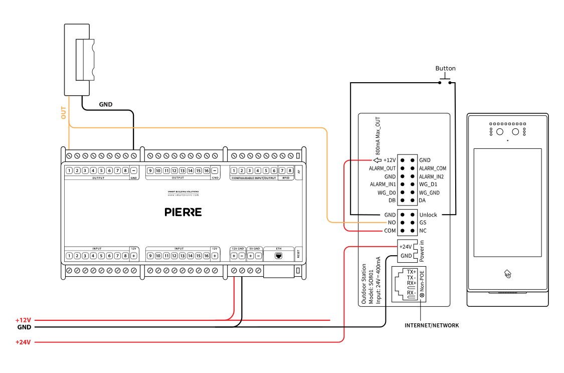
Pierre controller and Boston opens the door too (+ outside button via Boston)
Cables - Hybrid + button outside
| position | wires | diameter | type | comment |
|---|---|---|---|---|
| From Electric box to Boston Intercom | 2 | 1 mm² | H07V-K | +24V, GND |
| From Pierre to Lock | 2 | 1 mm² | H07V-K | OUT, GND |
| From Boston Intercom to Lock | 2 | 1 mm² | H07V-K | OUT, GND |
| From Network switch to Boston Intercom | 4 | 0.25 mm² | Cat5 UTP | LAN (RX+, RX-, TX+, TX-) |
| From Boston Intercom to Button | 2 | 0.5 mm² | H07V-K | UNLOCK, GND |
Schemes - Pierre controller opens the door via Boston
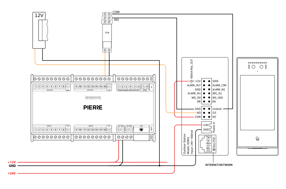
Only Boston intercom opens the door (Pierre controller opens via Boston)
Cables - Pierre controller opens the door via Boston
| position | wires | diameter | type | comment |
|---|---|---|---|---|
| From Electric box to Boston Intercom | 2 | 1 mm² | H07V-K | +24V, GND |
| From Pierre to Mechanical relay | 2 | 0.75 mm² | H07V-K | OUT, GND |
| From Mechanical relay to Boston Intercom | 2 | 0.75 mm² | H07V-K | UNLOCK, GND |
| From Boston Intercom to Lock | 2 | 1 mm² | H07V-K | OUT, GND |
| From Network switch to Boston Intercom | 4 | 0.25 mm² | Cat5 UTP | LAN (RX+, RX-, TX+, TX-) |
Schemes - Only Pierre controller opens the door
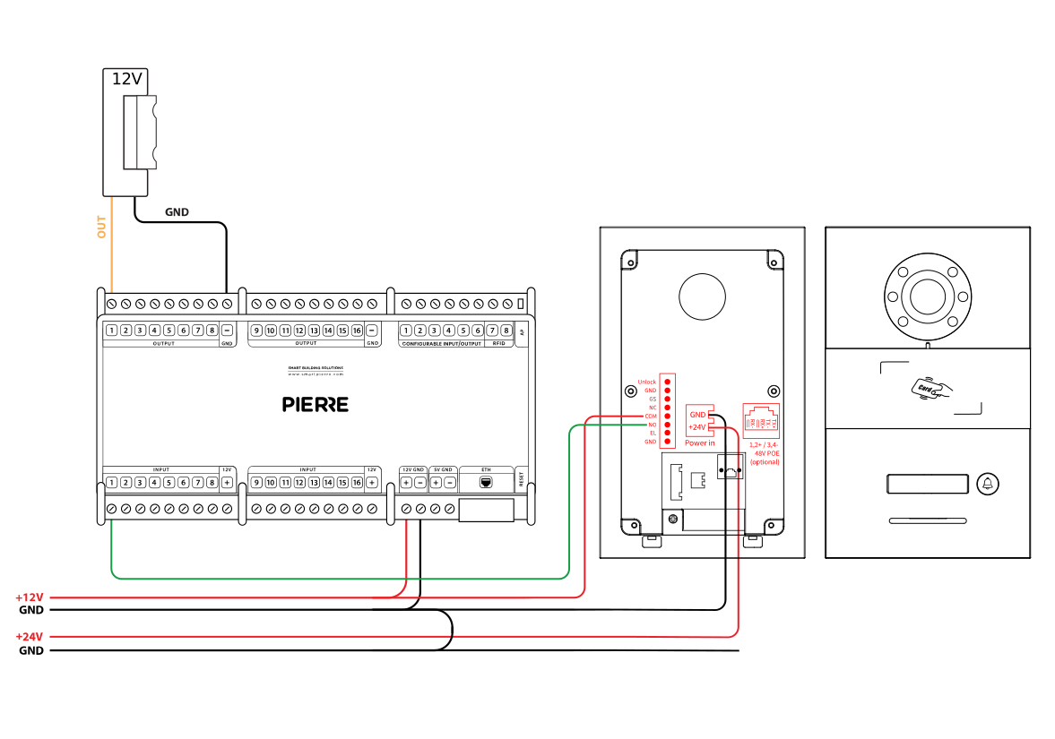
Only Pierre controller opens the door (Springfield opens via Pierre controller)
Cables - Only Pierre controller opens the door
| Position | wires | Diameter | type | comment |
|---|---|---|---|---|
| From Electric box to Springfield Intercom | 2 | 1 mm² | H07V-K | +24V, GND |
| From Pierre to Springfield Intercom | 2 | 0.5 mm² | H07V-K | +12V, SIGNAL |
| From Pierre to Lock | 2 | 1 mm² | H07V-K | OUT, GND |
| From Network switch to Springfield Intercom | 4 | 0.25 mm² | Cat5 UTP | LAN (RX+, RX-, TX+, TX-) |
Schemes - Only Springfield opens the door
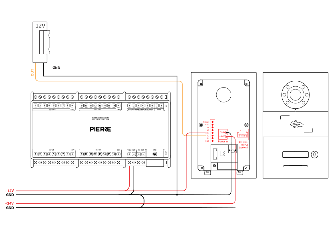
Only Springfield opens the door
Cables - Only Springfield opens the door
| position | wires | diameter | type | comment |
|---|---|---|---|---|
| From Electric box to Springfield Intercom | 2 | 1 mm² | H07V-K | +24V, GND |
| From Pierre to Springfield Intercom | 1 | 1 mm² | H07V-K | +12V |
| From Springfield Intercom to Lock | 2 | 1 mm² | H07V-K | OUT, GND |
| From Network switch to Springfield Intercom | 4 | 0.25 mm² | Cat5 UTP | LAN (RX+, RX-, TX+, TX-) |
Schemes - Hybrid (Springfield and Controller opens the door too)
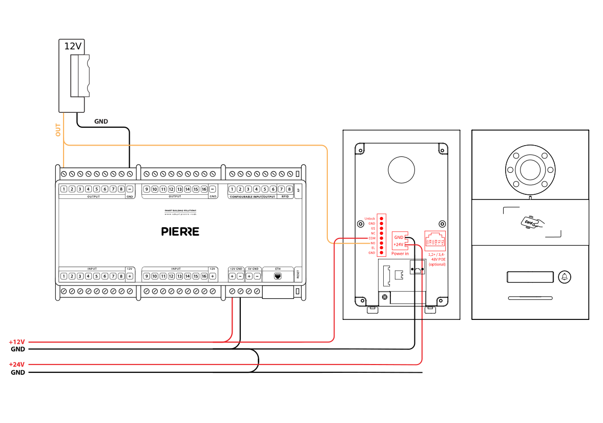
Pierre controller and Boston opens the door too
Cables - Hybrid (Springfield and Controller opens the door too)
| position | wires | diameter | type | comment |
|---|---|---|---|---|
| From Electric box to Springfield Intercom | 2 | 1 mm² | H07V-K | +24V, GND |
| From Pierre to Springfield Intercom | 1 | 1 mm² | H07V-K | +12V |
| From Springfield Intercom to Lock | 2 | 1 mm² | H07V-K | OUT, GND |
| From Pierre to Lock | 2 | 1 mm² | H07V-K | OUT, GND |
| From Network switch to Springfield Intercom | 4 | 0.25 mm² | Cat5 UTP | LAN (RX+, RX-, TX+, TX-) |
Troubleshooting
The system will continue to function locally without internet access, but remote access (such as controlling devices from a phone while away) will not be possible.
Yes, depending on the model, the intercom can support Power over Ethernet (PoE). Please check the product specifications for confirmation.
If you're using PIERRE displays, a separate indoor intercom unit is not needed, as the displays can function as indoor intercom units. The PIERRE app on mobile devices can also act as an intercom.
Yes, the intercom will still function locally without internet access, but you will not be able to receive intercom calls remotely from outside the local network.
No, the intercom will not ring on your phone without internet, but it will still ring on the indoor display unit.