
Power Supply 12V/1.25A (DIN)
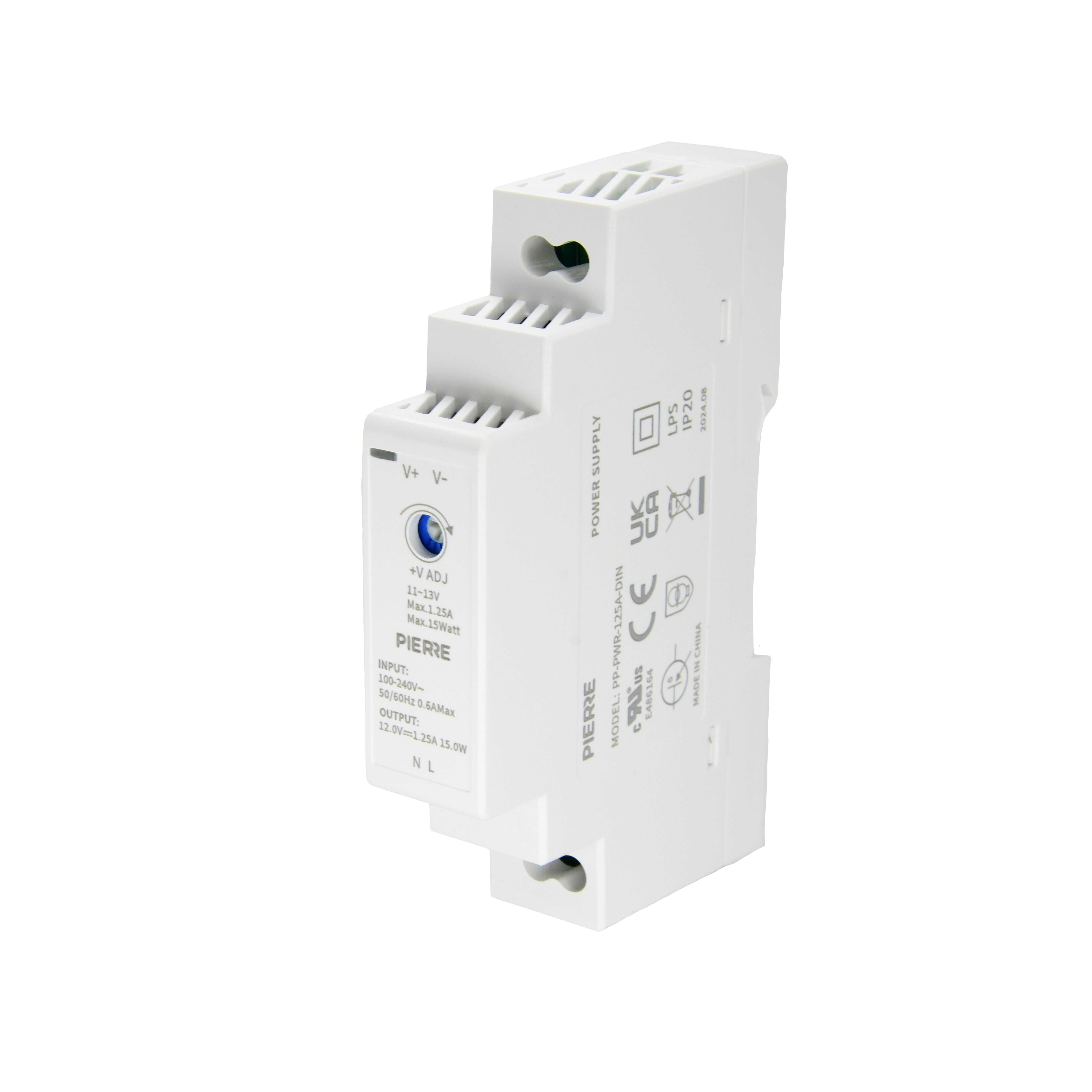
| SKU | PP-PWR-125A-DIN |
|---|---|
| Product line | PIERRE Pro |
| Category | Power Supplies |
| Manufacturer | YingJiao |
| Manufacturer SKU | YSD15S-1201250 |
| GTIN / EAN | 8606034720154 |
| HS code | 8504406020 |
Overview
The PIERRE Pro Power Supply operates with a 100-240V AC input and delivers a stable 12V DC output at 1.25A, with a maximum power of 15W. It efficiently converts AC to DC, providing the essential direct current required for powering smart home devices and automation components. The wide input voltage range ensures compatibility with global power grids.
The DIN rail compatibility allows for easy installation into electrical cabinets, making it an ideal solution for powering smart home systems. Engineered for high reliability, it provides stable and efficient power delivery, ensuring long-term performance in demanding environments.
Key features
100-240V AC input range, AC to DC conversion, 12V DC output, 1.25A current capacity, 15W maximum power, high-efficiency power delivery, DIN rail mountable
Technical specifications
| Electrical | |
|---|---|
| Input Power | 100-240V AC |
| Output Power | 12V DC 1.25A 15W |
| Efficiency | 85 % |
| Power Factor | 0.98 |
| Current | 1.25 A |
| Environmental | |
| Operating Temperature | -4°F ~ +158°F |
| Operating Temperature (°C) | -20°C ~ +70°C |
| Operating Humidity | 20%-90% RH, Non Condensing % RH |
| Storage Temperature | -40°C - +80°C |
| IP Rating | IP20 |
| Features | |
| LED Indicators | Yes |
| Physical | |
| Product Color | White |
| Mounting Type | DIN Rail |
| Wiring Requirements | N - Neutral, L - Live |
| Safety | |
| Safety Features | Overload protection, Over voltage protection, Short circuit protection |
Electrical & I/O
| DIN rail | 1 module(s) |
|---|
Pin layout
| Pin | Label | Type | Position |
|---|---|---|---|
| 1 | L | power_line | top |
| 2 | N | power_neutral | top |
| 3 | 12V+ | output_12v_plus | bottom |
| 4 | GND | power_gnd_out | bottom |
Physical & packaging
| Dimensions (L × W × H) | 18 × 59 × 92 mm |
|---|---|
| Weight | 71 g |
| Box dimensions (L × W × H) | 23 × 64 × 96 mm |
| Box weight | 82 g |
User manual
- 1. What you need
- 2. Product Description
- 3. Dimensions
- 4. Product specifications
- 5. Wiring
- 6. Functional Diagram
- 7. Derating Curve
- 8. Output Derating vs Input Voltage
1. What you need
Wired. Mains AC input, DIN-rail mounted. Provides 12 V DC for PIERRE devices such as the Controller; size the supply to the total current of everything connected.
2. Product Description
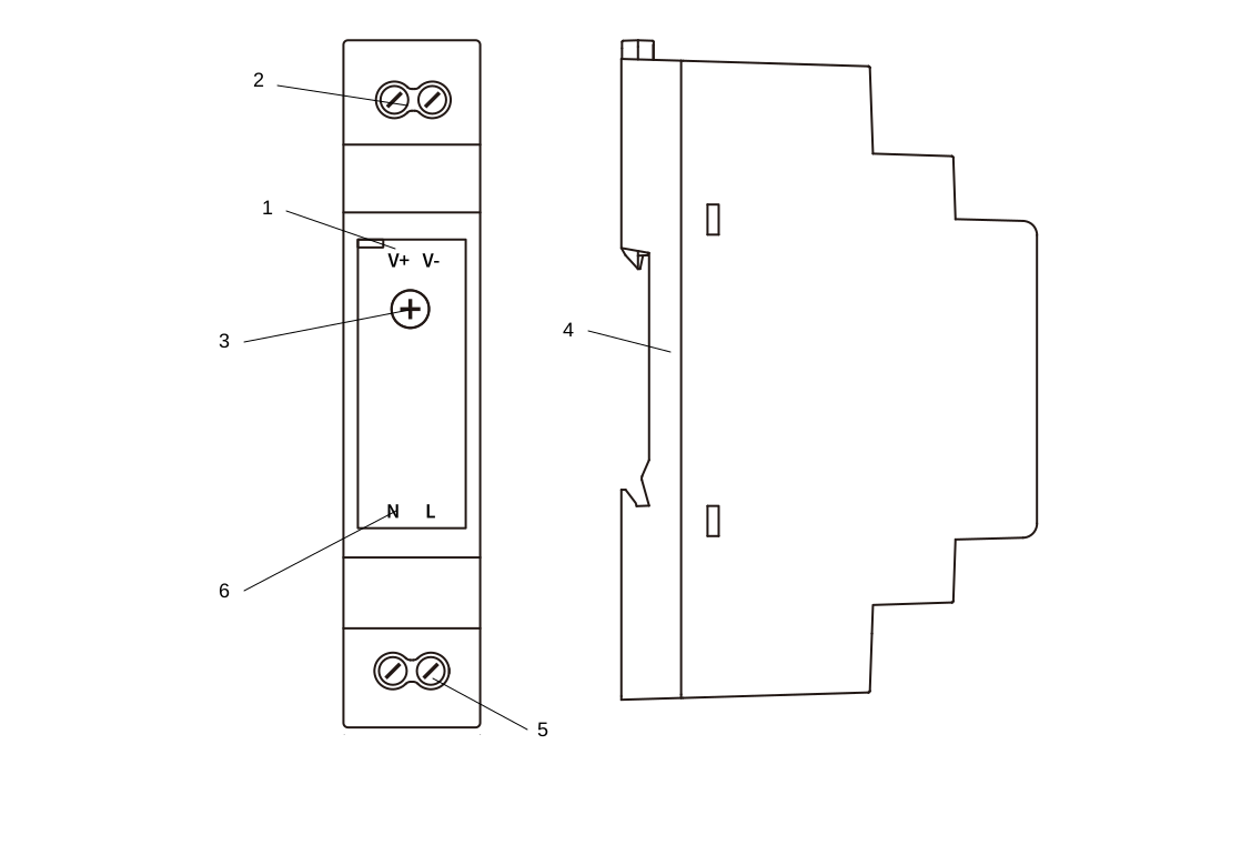
- V+, V-
- Upper connectors (green, black) - OUTPUT
- Voltage adjustment potentiometer
- DIN rail mounting
- Lower connectors (brown, blue) - INPUT
- N, L
3. Dimensions
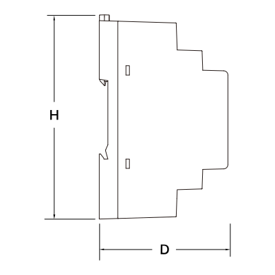
- H: 90 mm
- D: 58 mm
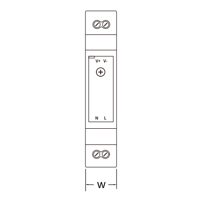
- W: 18 mm
4. Product specifications
5. Wiring
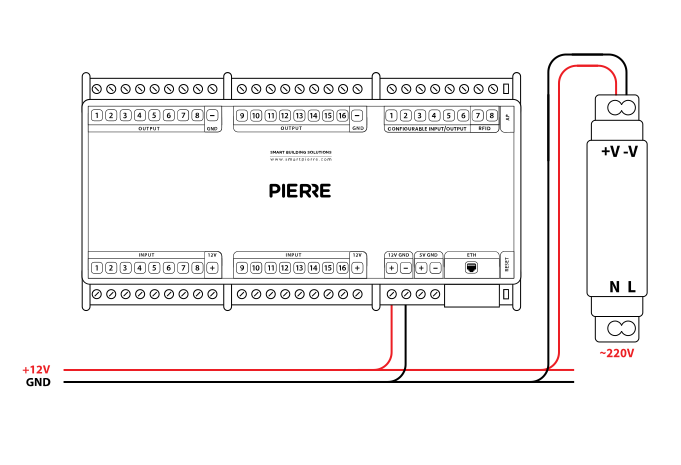
- Connect the AC input terminals to mains power: L (Live) and N (Neutral).
- The output terminals V+ and V− supply 12 V DC. Connect V+ to the 12 V input of the device and V− to its GND.
- Use the correct conductor cross-section and double-check polarity to avoid damaging connected devices.
- Example wiring: From Power supply to Controller
| Run | Wires | Cross-section | Cable type | Conductors |
|---|---|---|---|---|
| Example: From power supply to Controller | 2 | 0.75 mm² | NYM-J | +12 V, GND |
6. Functional Diagram
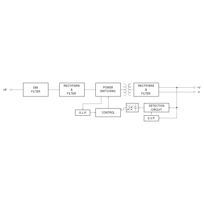
Functional Diagram – System Overview
The diagram shows the internal stages of a switching mode power supply (SMPS) from AC input to regulated DC output.
Block descriptions:
- I/P (Input): AC mains voltage is supplied to the power supply.
- EMI Filter: attenuates conducted and radiated electromagnetic interference and protects downstream components.
- Rectifiers & Filter (primary side): converts AC to DC and smooths the rectified voltage with capacitive filtering.
- Power Switching Stage: a high-frequency switching converter (typically a MOSFET) chops the DC voltage to drive the transformer; switching is controlled by PWM (pulse width modulation).
- Transformer: provides galvanic isolation between input and output and steps the voltage up or down.
- Rectifiers & Filter (secondary side): converts the high-frequency AC from the transformer back to DC and filters ripple and noise. Delivers the output rails +V and –V.
- Detection Circuit: monitors the output voltage and generates the feedback for regulation.
- Control Circuit: processes the feedback and adjusts the switching duty cycle for a stable DC output.
- O.L.P. (Over Load Protection): detects overload or short circuit on the output and limits the current or shuts the converter down.
- O.V.P. (Over Voltage Protection): disables the power supply if the output voltage exceeds the set limit.
7. Derating Curve
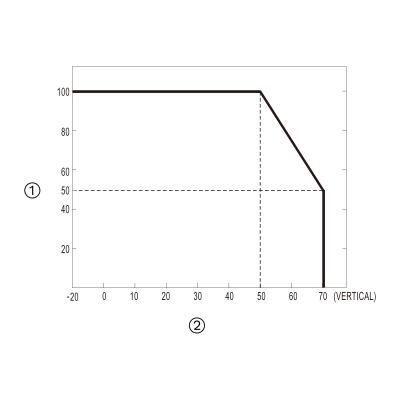
- Load (%)
- Ambient Temperature (°C)
8. Output Derating vs Input Voltage
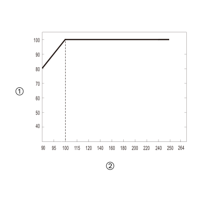
- Load (%)
- Input voltage (V AC), 60 Hz