
Mechanical Relay with Socket (16A 250V AC / 12V DC coil)
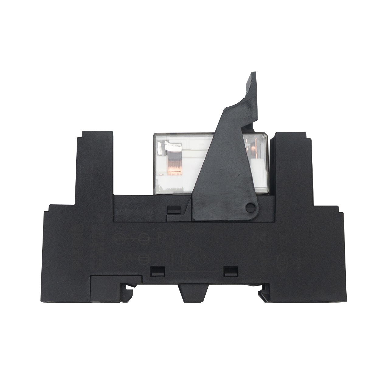
| SKU | PP-R1-M |
|---|---|
| Category | Relays |
| GTIN / EAN | 8606034721168 |
Overview
The Mechanical Relay with Socket is the interposing relay between a PIERRE controller and a mains load. The coil runs at 12 V DC, matching the controller output directly, and the single changeover contact switches up to 16 A at 250 V AC.
It plugs into a socket on 35 mm DIN rail, so the relay can be replaced without disturbing field wiring, and commons across a row of relays can be bridged with the PIERRE busbar range rather than wired terminal to terminal.
Where the circuit switches frequently, use the Solid State Relay with Socket instead, which has no contacts to wear.
Key features
- Contact rated 16 A @ 250 V AC
- Coil 12 V DC — drives directly from a controller output
- Single changeover contact (SPDT)
- DIN rail
- Relay replaceable without disturbing field wiring
Technical specifications
| Electrical | |
|---|---|
| Coil Voltage | 12 V DC |
| Contact Rating | 16 A @ 250 V AC (resistive) |
| Contact Material | Silver alloy (Ag alloy) |
| Contact Resistance | ≤100 mΩ |
| Max Switching Power | 4000 VA |
| Max Switching Voltage | 440 V |
| Max Switching Current | 16 A |
| Dielectric Strength | 5000 V AC coil–contact · 1000 V AC contact–contact · 2500 V AC between contact groups · 2000 V AC between adjacent socket terminals (1 min) |
| Surge Voltage | 10 kV (1.2/50 µs), coil to contact |
| Operate Time | ≤15 ms |
| Release Time | ≤8 ms |
| Insulation Resistance (500 V DC) | ≥1000 MΩ |
| Terminal Wire Size | 0.5 – 1 mm² |
| Terminal Screw Torque | 0.8 N·m |
| Relay | 1 changeover contact (SPDT) |
| Environmental | |
| Operating Temperature | -40 °C to +70 °C |
| Operating Humidity | 35 – 85 % RH |
| Storage Temperature | -40 °C to +55 °C |
| Vibration Resistance | 10–150 Hz, 10 g / 5 g |
| Shock Resistance | Impact 98 m/s², stability 980 m/s² |
| Physical | |
| Material | Socket PA6 + GF20 % (RoHS), UL94 V-0; brass terminals, tin-plated |
| Mounting Type | DIN Rail |
Electrical & I/O
| DIN rail | 1 module(s) |
|---|
Pin layout
| Pin | Label | Type | Position |
|---|---|---|---|
| 1 | NO | relay_no | top |
| 2 | NC | relay_nc | top |
| 3 | COM | relay_com | top |
| 4 | A1 | coil_a1 | bottom |
| 5 | A2 | power_gnd_in | bottom |
Physical & packaging
| Dimensions (L × W × H) | 15 × 58 × 75 mm |
|---|---|
| Weight | 60 g |
| Box dimensions (L × W × H) | 15 × 58 × 75 mm |
| Box weight | 60 g |
User manual
- 1. Product Description
- 2. Product Specifications
- 3. Connections Diagram
- 4. Relay Dimensions
- 5. Socket Dimensions
- 6. Relay Characteristics
1. Product Description
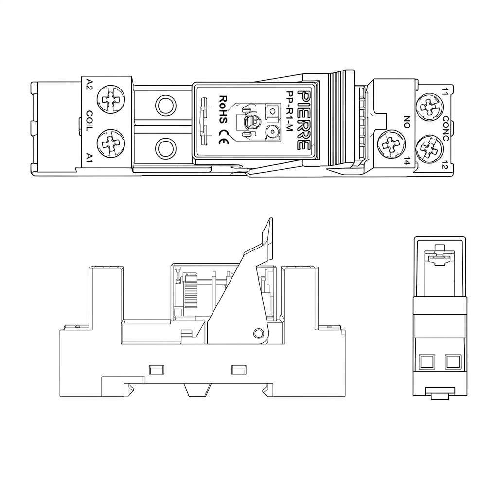
DIN-rail relay module that lets a PIERRE controller switch mains or high-current loads. The coil is driven from a 12 V DC signal output pin on the controller, with a second wire back to the controller's GND to close the circuit. Coil polarity is not critical — A1 and A2 can be interchanged.
The contact side is a potential-free changeover, fully isolated from the 12 V control side:
- 11 — COM, the common pole; the switched line feeds in here
- 12 — NC, connected to 11 when the coil is off
- 14 — NO, connected to 11 when the coil is on
2. Product Specifications
3. Connections Diagram
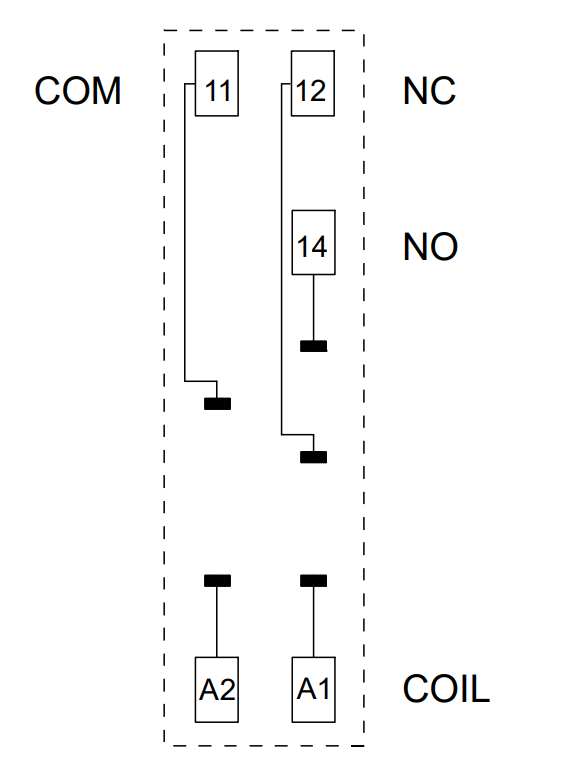
Wire the relay as follows:
- A1 / A2 – connect the relay coil supply here. Apply the rated coil voltage across A1 and A2 to activate the relay, these are the connections from PIERRE controllers output pin and GND.
- 11 – COM – common contact.
- 12 – NC – normally closed contact. 11 and 12 are connected when the relay coil is OFF.
- 14 – NO – normally open contact. 11 and 14 are connected when the relay coil is ON.
4. Relay Dimensions
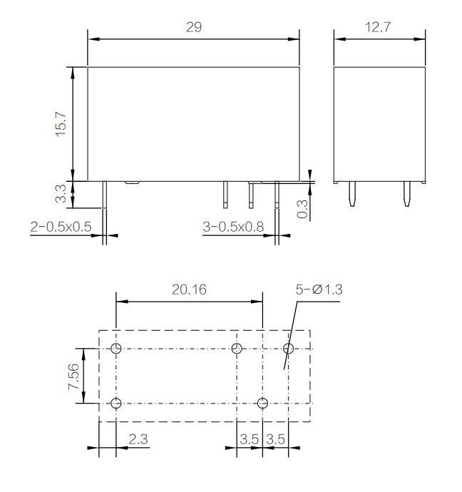
Slim plug-in relay: 29 × 12.7 × 15.7 mm body (3.3 mm pin length below the base).
Five terminals: 2 coil pins 0.5 × 0.5 mm and 3 contact pins 0.5 × 0.8 mm.
PCB footprint: 5 × Ø1.3 mm holes on a 20.16 × 7.56 mm pattern, with 2.3 mm and 2 × 3.5 mm pin spacing along the length.
5. Socket Dimensions
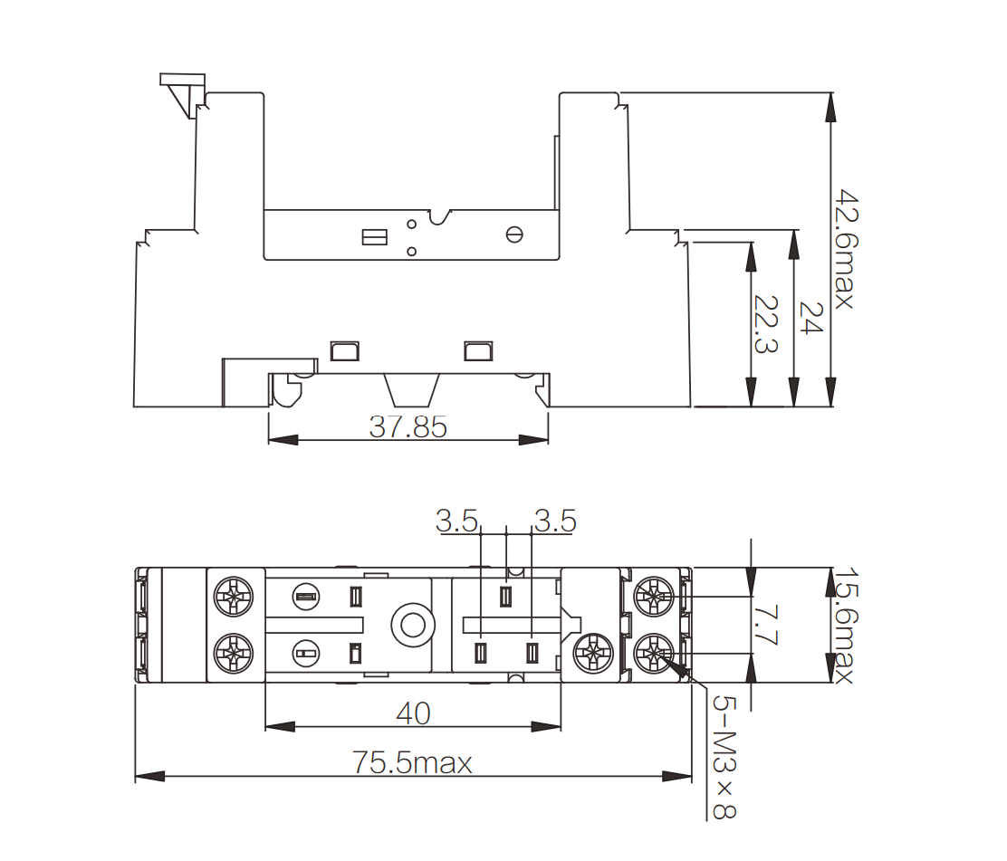
Dimensions: 75.5 × 15.6 × 42.6 mm max, 37.85 mm DIN-rail base width.
Screws: Five M3 × 8 screw terminals; 40 mm terminal span with 2 × 3.5 mm pin spacing.
6. Relay Characteristics
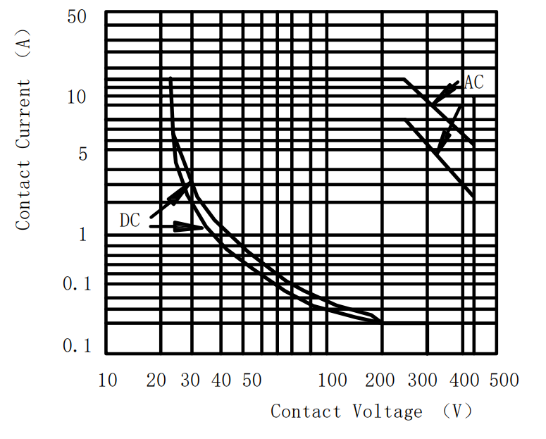
Maximum switching power
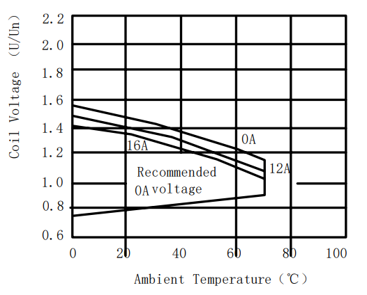
Coil operating temperature curve (AC)
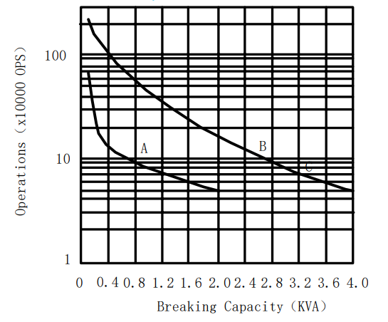
Electrical durability curve