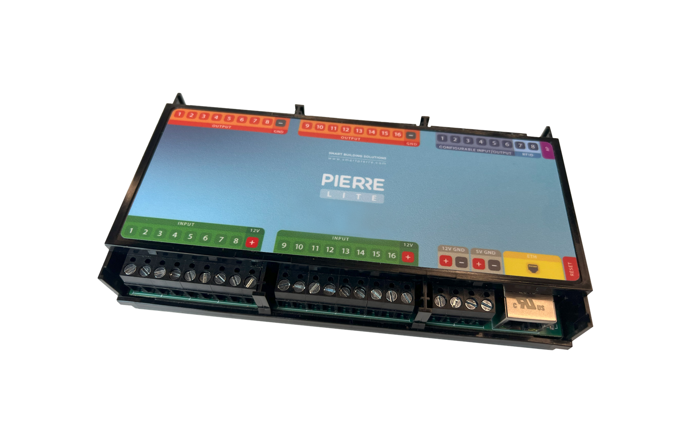
Solution - PID Regulated HC
Description
PID controlled heating and cooling enables continuous valve control using a 0–10 V analog signal.
To control such systems, the following components are required:
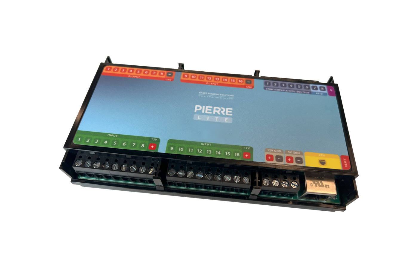
- PIERRE Controller Pro or Lite
- 0–10 V adapter connected to the Controller
- Temperature sensor
Unlike traditional ON/OFF control, where the valve is either fully open or fully closed, PID control allows continuous adjustment of the valve position. The PIERRE system continuously calculates the required 0–10 V control signal based on the difference between the measured temperature and the set temperature, and adjusts the valve opening accordingly.
This provides more accurate and stable temperature regulation and can reduce frequent system switching between ON and OFF states.
Difference Between PID and ON/OFF Control
ON/OFF Control
With ON/OFF control, the valve typically operates in two states:
- fully open, or
- fully closed,
depending on the heating or cooling demand.
PID Control
With PID control, the system continuously adjusts the valve opening level.
As the measured temperature approaches the desired setpoint, the controller continuously modifies the valve position to maintain the target temperature as accurately and stably as possible.
Configuration
- Open the required Controller in the PIERRE Partner application.
- Navigate to the Configurable I/O menu.
- Select the PID Regulated Heating/Cooling type.
- Select the Pin connected to the 0–10 V valve actuator control input.
- Select the temperature sensor used for PID regulation.
- Configure the required information:
- Name
- Role
- Image
- Save the configuration.
Application Areas
PID control can be used in heating and cooling systems where the controlled valve actuator supports 0–10 V control.
Typical applications include:
- underfloor heating systems,
- ceiling heating and cooling systems,
- fan coil systems with 0–10 V controlled valves,
- zone control systems,
- applications where precise and continuous temperature regulation is required.
Technical Notes
- The function requires a 24 V or 230 V valve actuator with a 0–10 V control input. Traditional thermo-electric ON/OFF actuators cannot be controlled using this method.
- A suitable temperature sensor is required for PID regulation. The sensor is typically used to measure the supply water temperature. For this purpose, a waterproof DS18B20 temperature sensor can be used, which must be properly attached to the supply pipe.
- To ensure accurate measurement, the DS18B20 sensor must be installed with proper thermal contact to the pipe and sufficiently insulated from the surrounding ambient temperature.
- The 0–10 V control signal cable must be routed separately from power cables, especially 230 V wiring. The use of a shielded cable is recommended to reduce interference.
- For a 24 V DC powered valve actuator, the correct reference potential for the 0–10 V control signal requires connecting the GND point of the PIERRE 12 V power supply with the GND point of the valve actuator’s 24 V power supply, according to the PIERRE wiring diagram.
- The 24 V power supply must never be connected to the PIERRE Controller’s 0–10 V analog output. The 24 V supply is used only to power the valve actuator, while the PIERRE Controller’s 0–10 V output provides only the control signal.
- For a 230 V AC powered valve actuator with 0–10 V control, the power supply and 0–10 V control signal wiring must always be installed according to the valve actuator manufacturer's wiring diagram.
- The installation must always be carried out according to:
- the PIERRE wiring diagram,
- the valve actuator manufacturer's documentation,
- and the electrical design documentation of the project.
Schemes
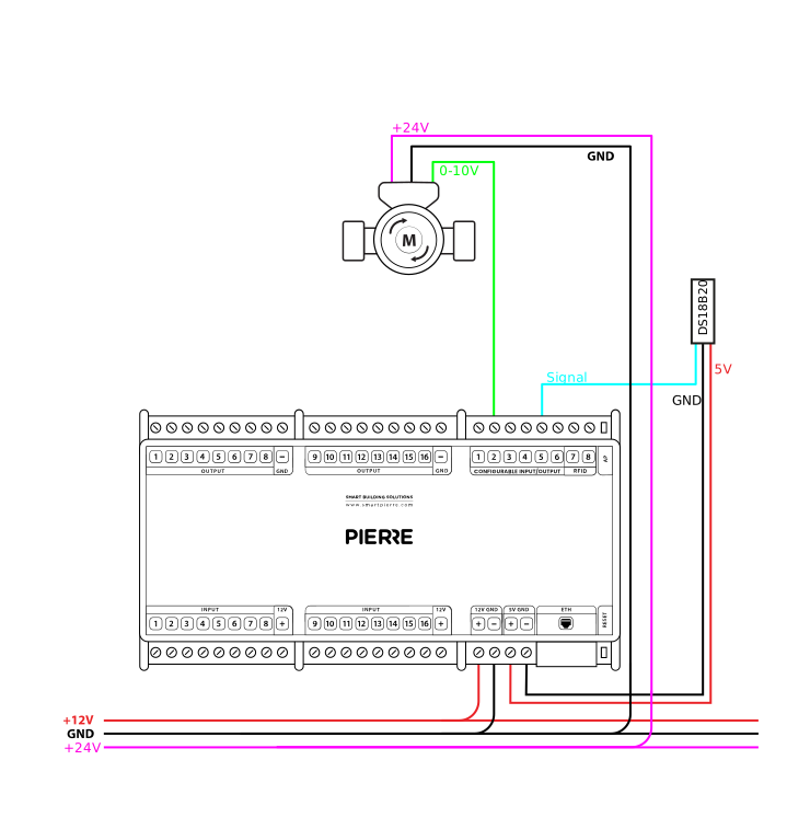
PID regulated HC - 24V power supply and 0-10V control
Cables
| Position | Wires | Diameter | Type | Comment |
|---|---|---|---|---|
| From PIERRE to Mixing valve | 3 | 1 mm² | H07V-K | 24V, GND, SIGNAL |
| From PIERRE to Temperature sensor | 3 | 0,5 mm² | H07V-K | 5V, GND, SIGNAL |