PIERRE Partner - Generic Modbus
Description
PIERRE Fields
This section defines the concept of PIERRE generic modbus, which represent the logical connection between Modbus registers and system-level parameters in the PIERRE BMS.
Each field corresponds to a physical parameter of a Modbus device — a state, measurement, or control value — that can be monitored and/or modified through the PIERRE Controller PRO.
Understanding these fields is essential for correctly mapping registers during device integration.
Active
Type: Read-only Description: Indicates whether the device is currently performing its function. For example, a fan coil’s Active field shows whether the fan is currently circulating air to heat or cool the room.
If the Modbus device does not provide a dedicated register for this, the Active field can mirror the Mode register.
Value range:
0→ Inactive1→ Active
Mode
Type: Read/Write Description: Defines the operational state of the device — typically ON/OFF or AUTO. This field controls whether the device is powered or in standby mode.
If the device reports “inactive” even when switched ON (for example, when temperature setpoint is reached), the Activefield should monitor the same register.
Value range:
0→ OFF1→ ON2→ Auto Mode
Target
Type: Read/Write Description: Represents the setpoint of the controlled device. Usually corresponds to the desired temperature, humidity, or other controlled physical variable.
Examples:
- Temperature setpoint of an HVAC unit
- Flow or pressure setpoint for a pump or valve
Intensity
Type: Read/Write Description: Defines the operational intensity level of the device — for example, fan speed or ventilation power. Used primarily in HVAC systems with adjustable fan or compressor levels.
Value
Type: Read-only Description: Provides measurement data from the device — typically sensor readings such as:
- Temperature
- Humidity
- Water flow
- Electrical current or voltage
This field is purely informative and cannot be modified.
Heating Season
Type: Read/Write Description: Determines whether the device operates in heating or cooling mode.
Value range:
0→ Cooling1→ Heating
Used in HVAC units or heat pumps with seasonal operation modes.
Mode Season
Some devices combine Mode and HeatingSeason into a single Modbus register. In this case, heating/cooling I/O types (e.g., fan coils) should enable the “Combined Mode” option.
To handle this properly:
- Add a read-only Mode field to translate register values into logical ON/OFF/AUTO states.
- Add a read-write HeatingSeason field to represent seasonal control (heating/cooling).
Refer to Chapter: Read and Write Functions for translation examples.
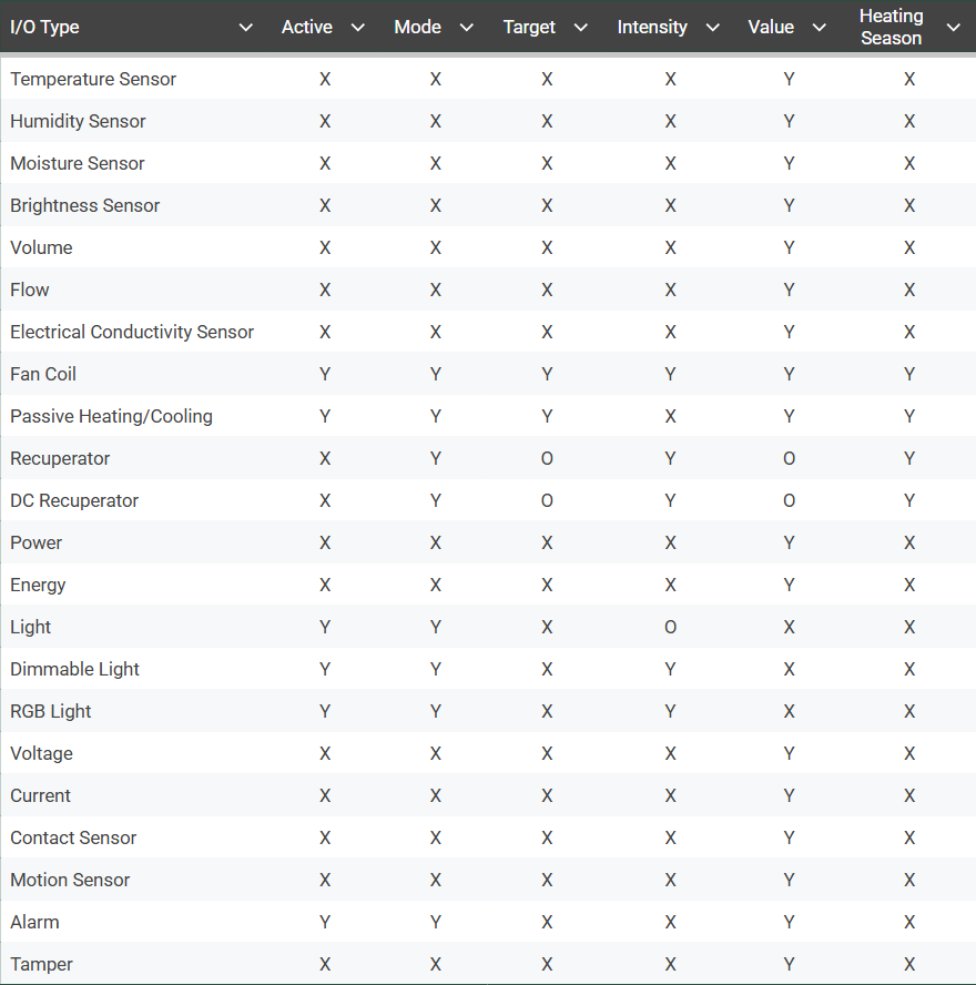
Required Fields by I/O Type
The table below lists which fields are required (Y), optional (O), or not required (X) for each I/O type.
Add caption...
-
Address – Enter the address of the Modbus register or coil.
-
Type – Select the Modbus register type:
-
Coil – Used for coil-based data.
-
Discrete Input – Used for discrete input data.
-
Input Register – Used for read-only input registers.
-
Holding – Uses FC03 – Read Holding Registers for reading and FC06 – Write Single Register for writing.
-
Holdings – Uses FC03 – Read Holding Registers for reading and FC16 (0x10) – Write Multiple Registers for writing.
-
-
Data Type – Defines how the data is interpreted. Select the data type according to the format used by the Modbus device:
-
UInt16 – 16-bit unsigned integer.
-
UInt32 – 32-bit unsigned integer.
-
UInt64 – 64-bit unsigned integer.
-
Int16 – 16-bit signed integer.
-
Int32 – 32-bit signed integer.
-
Int64 – 64-bit signed integer.
-
Float – Floating-point value, typically used for measurements with decimal values, such as temperature or energy.
-
-
Read Function – Applies a transformation to the value read from the Modbus device. This can be used when the raw Modbus value needs to be converted into the value required by PIERRE:
-
Divide – Divides the read value by a specified value.
-
Multiply – Multiplies the read value by a specified value.
-
Swap – Changes the byte or word order of the received value.
-
Mask – Extracts specific bits from the received value.
-
Add – Adds a specified value to the received value.
-
Subtract – Subtracts a specified value from the received value.
-
Bit Shift – Shifts the bits of the received value left or right.
-
-
Write Function – Applies a transformation to the value before it is written to the Modbus device:
-
Divide – Divides the value before writing it to the device.
-
Multiply – Multiplies the value before writing it to the device.
-
Swap – Changes the byte or word order before writing the value.
-
Mask – Applies a bit mask to the value before writing it.
-
Add – Adds a specified value before writing the value.
-
Subtract – Subtracts a specified value before writing the value.
-
Bit Shift – Shifts the bits of the value left or right before writing it.
-
-
Poll Interval – Defines how frequently PIERRE reads the value from the Modbus device.
-
Access Control – Defines how the register can be accessed:
-
Read & Write – The register can be both read from and written to.
-
Read – The register can only be read from the device.
-
Write – The register can only be written to the device.
-
-
Loopback – Enables or disables loopback for the register field.
Word Swap is an I/O-level setting for Modbus Generic I/O. It is used when a multi-register value, such as a 32-bit, 64-bit, or Float value, is stored in a different word order than expected by PIERRE.
A Modbus register is 16 bits. Larger values use multiple consecutive registers. For example, a 32-bit value uses two 16-bit registers. Depending on the Modbus device, these two words may be stored in different orders.
Without Word Swap, PIERRE expects the standard word order. When enabled, PIERRE reverses the word order when reading the value from the device.
For example, a 32-bit value can be stored as:
- Normal word order: High Word → Low Word
- Word-swapped: Low Word → High Word
If the Modbus device uses word-swapped values and Word Swap is not enabled, PIERRE may interpret the received data incorrectly, resulting in an invalid value.
Word Swap is applied to the entire Modbus Generic I/O, not to individual register fields. It affects the read operation only.
For 16-bit values, Word Swap has no effect because there is only one word to process.
For 32-bit and Float values, the two 16-bit words are exchanged.
For 64-bit values, the word order within each 32-bit section is exchanged.
Note: Word Swap changes the word order, not the byte order within each word. It should not be confused with the Swap option available under the Read Function or Write Function. The two functions serve different purposes.
Register examples
When you add an I/O to a Generic Modbus device, every field you want to read or control has to be mapped to a register on that device. This lesson shows how a register mapping is configured, using a concrete example.
What You Need
- The device documentation, which lists the register addresses and what each one holds.
- The data type and the access mode of each register.
- The serial parameters of the line, if the device is connected over Modbus RTU.
The Example
The register definitions used here come from a Clivet HVAC system. It uses a three-wire proprietary bus and connects to PIERRE through a Midea Modbus Gateway, over either the RTU or the TCP interface.


Single or split registers for a field
Some manufacturers specify a single read/write holding register for the same parameter that can be used for both monitoring and control of a parameter, like with the PIERRE T series wall thermostats, while other manufacturers specify two separate registers for reading and writing the same parameter, as with the above example, where a holding register is used for modifying the set temperature while a reading register is used for polling the current value. This means that for a device like this, two Target fields have to be added with two separate register configurations, since changes made to the set temperature and other parameters with a wall thermostat are only guaranteed to be present in the input register.
Notes
- Each PIERRE Field must be linked to at least one Modbus register.
- The data type, read/write access, and scaling functions are defined in the Register Configuration section.
- When integrating custom devices, ensure all mandatory fields are included for consistent operation within the PIERRE BMS.
PIERRE Generic Modbus setup

Modbus RTU
Select the Controller.
For Modbus RTU configuration, select the Configurable I/O tab.
Tap Add and select Modbus RTU.
Required fields:
Name – Enter a name for the Modbus device.
Role – Select the appropriate Role.
TX – Select the TX pin assigned to the controller.
RX – Select the RX pin assigned to the controller.
Baud – Select the Modbus communication baud rate. Available values range from 2400 to 115200 baud.
Parity – Select the parity setting used by the Modbus device.
Stop Bits – Select the number of stop bits used by the Modbus device.

Modbus TCP
Select the Controller.
For Modbus TCP configuration, select the Services tab.
Tap Add and select Modbus TCP.
Required fields:
Name – Enter a name for the Modbus device.
Role – Select the appropriate Role.
Host – Enter the IP address or hostname of the Modbus TCP device.
Port – Enter the TCP port used by the Modbus device.
RTU over TCP – Enable this option for devices that use Modbus RTU communication over a TCP socket.
After creating a Modbus TCP or Modbus RTU device on the controller, you can add a Modbus Generic I/O from the Devices tab.
The Modbus Generic I/O allows you to configure the required Modbus registers and use them within the PIERRE system.

Step 3
Enter a name for the Generic Modbus device.
The Address field specifies the Modbus Unit Identifier. Refer to the documentation of the target device for the correct address.
Click Add new I/O type to add a predefined type for a supported Modbus device.
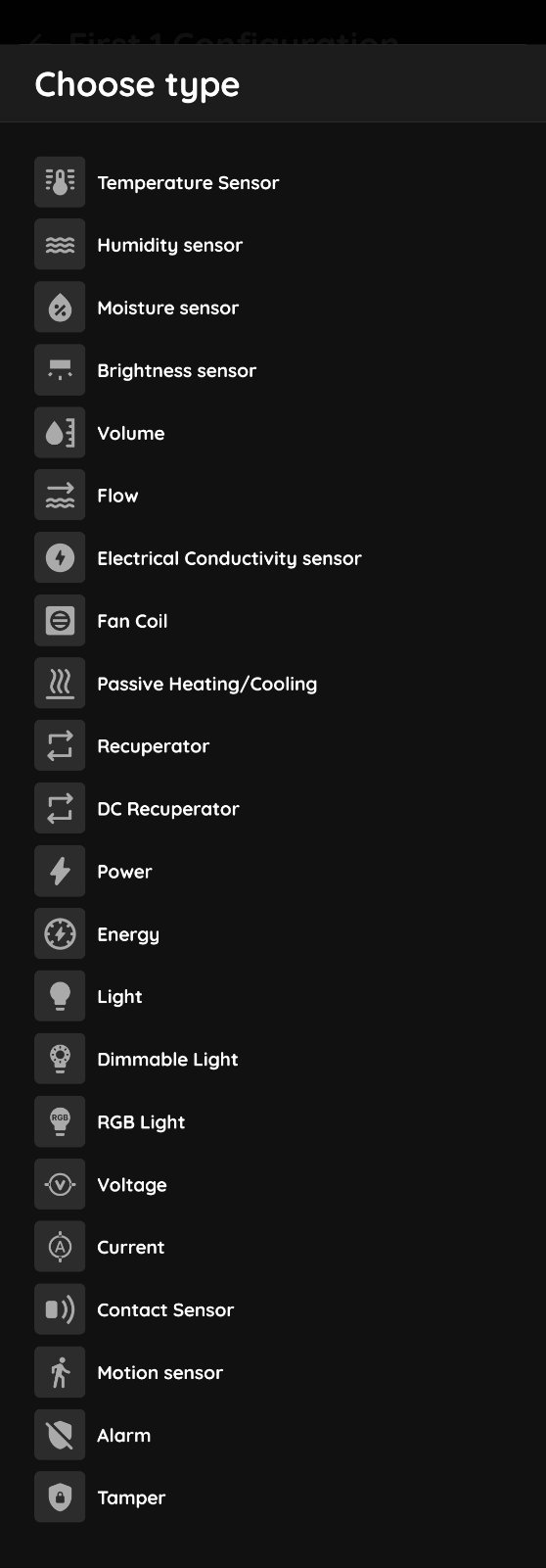
Step 4
Select the Modbus Generic I/O type for a custom Modbus device.
Here you can find all supported device types, including Fan Coil, Energy, Temperature Sensor, Volume, and more.
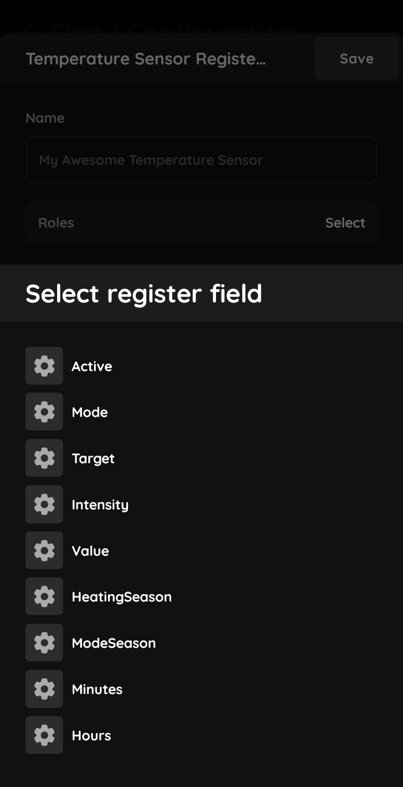
Register fields
After creating a Modbus Generic I/O, tap Add new I/O type to select a predefined device type that can be integrated with PIERRE.
Select the required I/O type, such as a Temperature Sensor. Depending on the selected I/O type, you may need to add one or more Modbus register fields.
Use the table above to select the correct register fields for each Modbus Generic I/O type.
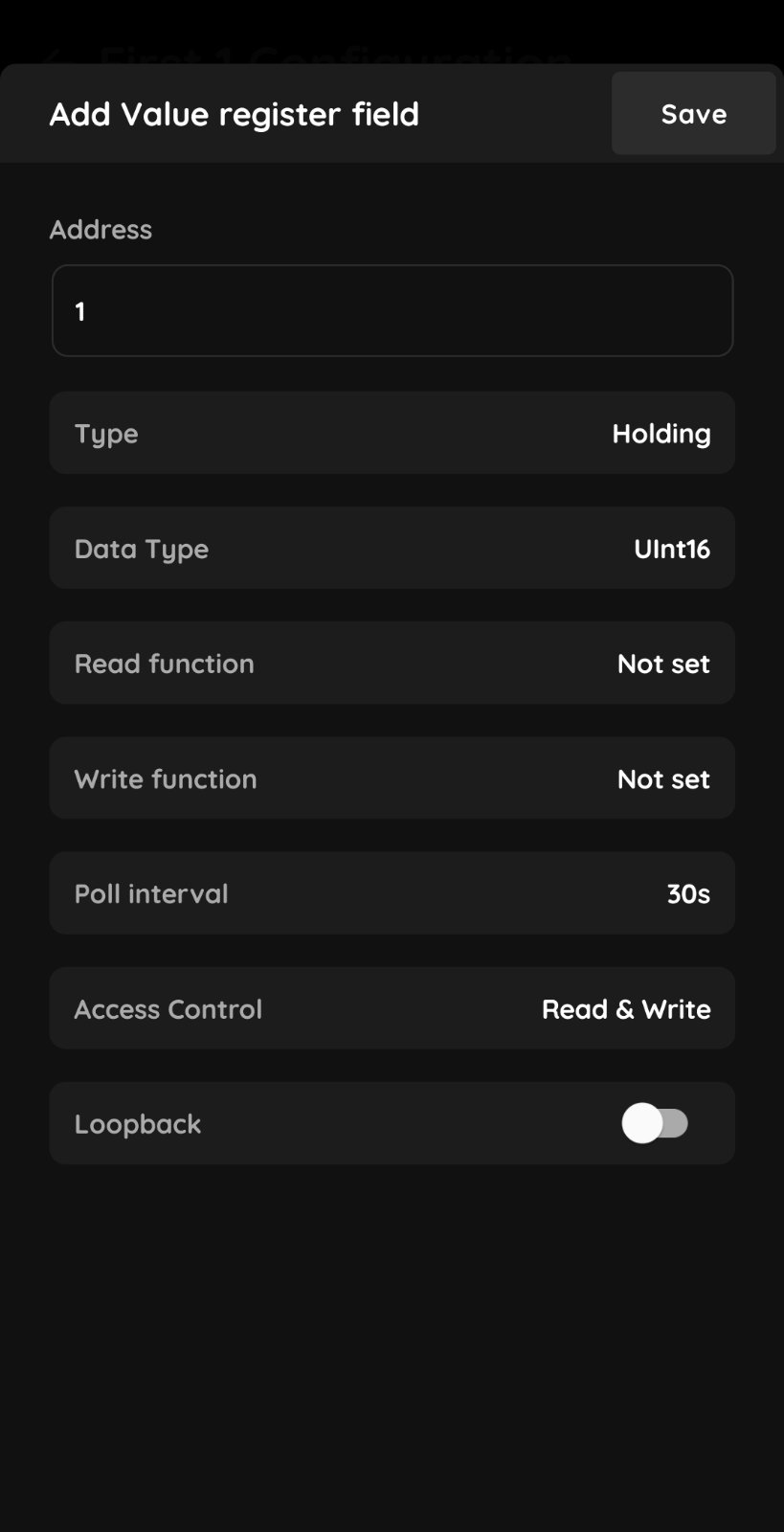
Register fields
Address – Enter the address of the Modbus register or coil.
Type – Select the Modbus register type:
Coil – Used for coil-based data.
Discrete Input – Used for discrete input data.
Input Register – Used for read-only input registers.
Holding – Uses FC03 – Read Holding Registers for reading and FC06 – Write Single Register for writing.
Holdings – Uses FC03 – Read Holding Registers for reading and FC16 (0x10) – Write Multiple Registers for writing.
Data Type – Defines how the data is interpreted. Select the data type according to the format used by the Modbus device:
UInt16 – 16-bit unsigned integer.
UInt32 – 32-bit unsigned integer.
UInt64 – 64-bit unsigned integer.
Int16 – 16-bit signed integer.
Int32 – 32-bit signed integer.
Int64 – 64-bit signed integer.
Float – Floating-point value, typically used for measurements with decimal values, such as temperature or energy.
Read Function – Applies a transformation to the value read from the Modbus device. This can be used when the raw Modbus value needs to be converted into the value required by PIERRE:
Divide – Divides the read value by a specified value.
Multiply – Multiplies the read value by a specified value.
Swap – Changes the byte or word order of the received value.
Mask – Extracts specific bits from the received value.
Add – Adds a specified value to the received value.
Subtract – Subtracts a specified value from the received value.
Bit Shift – Shifts the bits of the received value left or right.
Write Function – Applies a transformation to the value before it is written to the Modbus device:
Divide – Divides the value before writing it to the device.
Multiply – Multiplies the value before writing it to the device.
Swap – Changes the byte or word order before writing the value.
Mask – Applies a bit mask to the value before writing it.
Add – Adds a specified value before writing the value.
Subtract – Subtracts a specified value before writing the value.
Bit Shift – Shifts the bits of the value left or right before writing it.
Poll Interval – Defines how frequently PIERRE reads the value from the Modbus device.
Access Control – Defines how the register can be accessed:
Read & Write – The register can be both read from and written to.
Read – The register can only be read from the device.
Write – The register can only be written to the device.
Loopback – Enables or disables loopback for the register field.
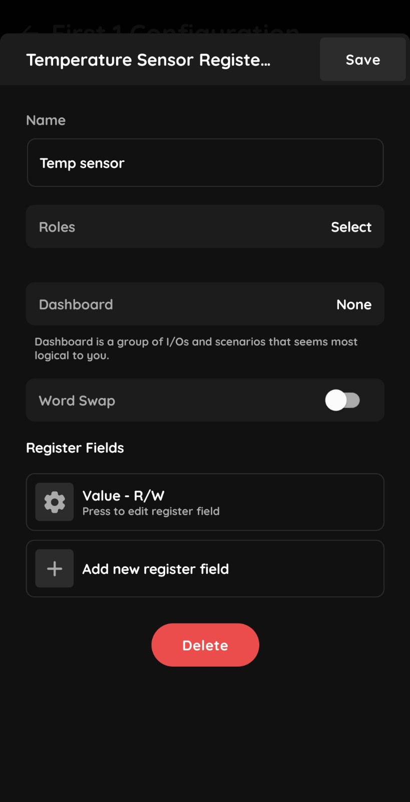
Device setup
Register configuration parameters
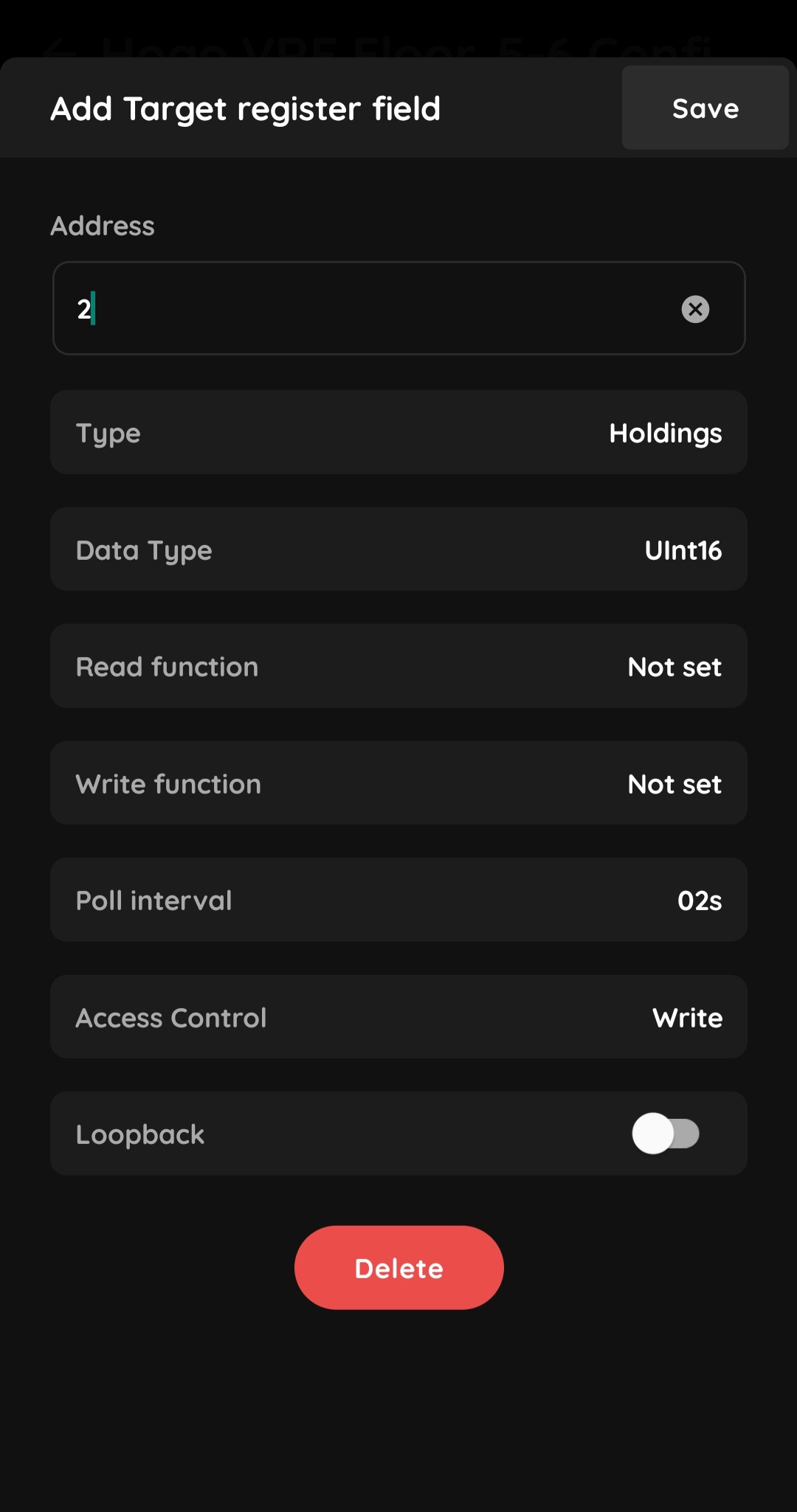
Address
Modbus registers must be addressed according to the addressing scheme specified by the manufacturer in order to access them.
Note that the register addresses defined in the manufacturer's documentation are sometimes different from the protocol addresses that must be used for Modbus communication. For example, with the Midea device described above, the manufacturer specifies the protocol address for input registers as [Register Address] − 30001 and for holding registers as [Register Address] − 40001. However, based on experimental testing, holding register addresses only require 40000 to be subtracted.
This means that the register address for the Target field is 2 for reading the parameter and 4 for modifying it.

Type (Register)
This refers to the register type and the Modbus function code used to access the register.
In most cases, manufacturers use Holding Registers for both reading and writing, or Input Registers for reading data and Holding Registers for writing data.
In the example above, the Target field used for reading is configured as Input, while the Target field used for writing is configured as Holdings.

Data Type
A single Modbus register contains two bytes (16 bits) of data. In most cases, when controlling a device such as a fan coil, a field is handled as a single Modbus register containing an unsigned integer value.
However, some devices that provide precise physical measurements, such as smart electricity meters or heat meters, may use multiple consecutive Modbus registers to store larger values.
For these cases, refer to the datasheet of the target device and select the appropriate Data Type.

Read and Write Functions
Modbus device manufacturers specify how the data in each register should be handled. In the PIERRE application, you can use the Read Function and Write Function options to specify how the data should be processed.

Divide, multiply, add, subtract
In the example used to illustrate the configuration process, the Input Register for the Target field specifies that the stored temperature value is multiplied by 10. This means that after reading the value, we need to divide it by 10 to obtain the actual temperature.
Therefore, we need to add Read Function → Divide with Data = 10.

Swap
For other values, the Swap function can be used for fields such as Heating Season and Mode.
For example, if a thermostat specifies that the value 0 corresponds to OFF and the value 1 corresponds to ON, but PIERRE requires the value 2 for AUTO, the value can be remapped using the Swap function.
Open the Read Functions menu and tap Add data pair.

Swap 1
Tap Add data pair to create a mapping between Modbus values and PIERRE values.
For example:
Modbus Value: 1
PIERRE Value: 2
Each pair defines how an incoming Modbus value is translated into the corresponding PIERRE value.
You can add multiple pairs if the device supports several operating modes.

Swap 2
After defining all pairs, the function will appear in the list, for example, as “Swap 1 → 2”.
Tap Done to save the configuration.
From now on, whenever PIERRE reads the Modbus register, the system will automatically apply the defined mapping.
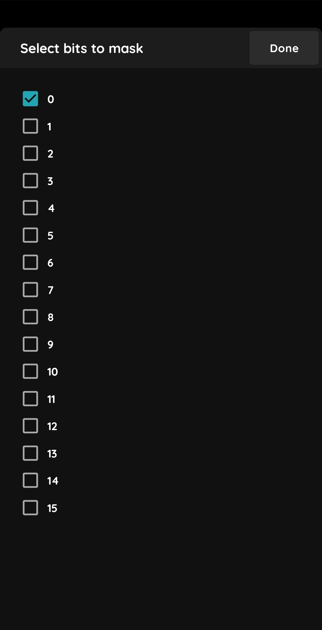
Maks
Sometimes a register contains two bytes, or 16 bits, of data, but only a few of those bits are relevant to us. For example, a register may use bit 0 to indicate the Active state.
In this case, the Mask function can be used to extract the relevant bit from the register value.

Mask 1
Set Read function
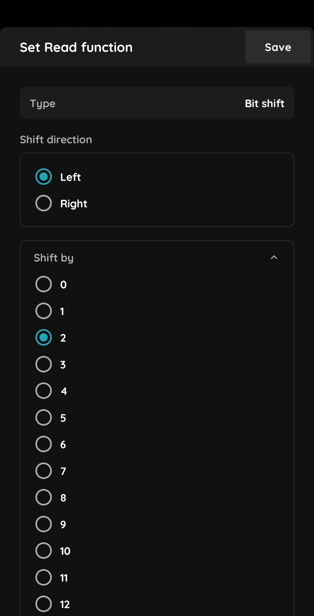
Bit shift
Similar to the scenario above, you may have a parameter such as Intensity with intensity levels ranging from 0 to 3, while the corresponding data is stored in bits 2 and 3 of the register.
In this case, the values need to be shifted left by two bits, resulting in the following mapping:
0 → 0
1 → 4
2 → 8
3 → 12
This could be achieved using a Swap function, but using a Bit Shift is more efficient. Set the Bit Shift function to shift the value left by 2 bits.
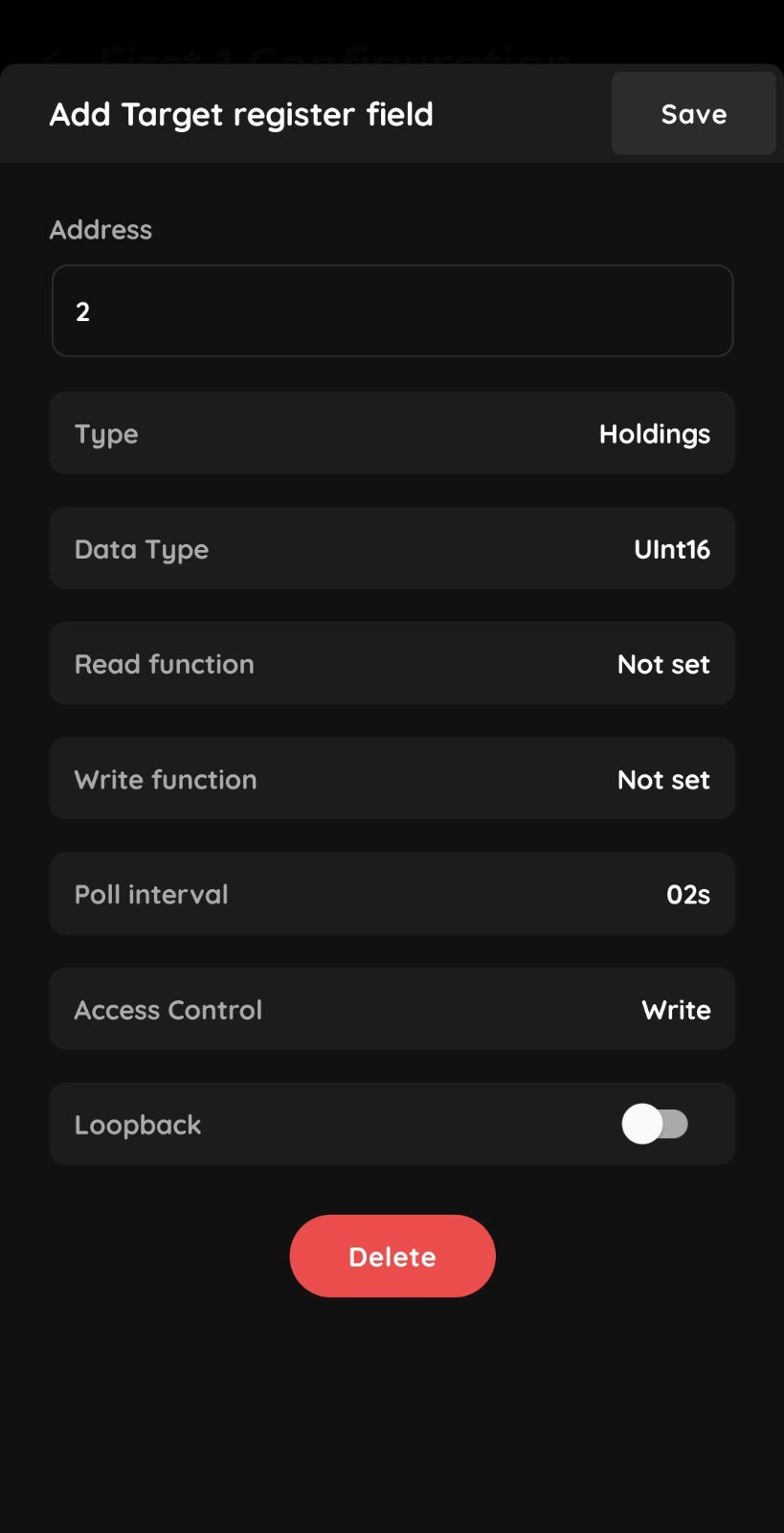
Poll interval
Poll Interval:
The PIERRE BMS periodically reads the data specified from a Modbus device. This configuration parameter determines how frequently the data is read for each field.
By default, the Value field is set to 30 seconds, as it is assumed to contain slowly changing physical values. All other fields are set to 2 seconds, as these values may change abruptly due to user interaction.
Only modify the default values when absolutely necessary, as changing them may affect the responsiveness of the entire system.
Access Control:
Depending on whether a parameter is monitored and controlled using the same register or separate read and write registers, the Access Control should be set to Read & Write, Read, or Write, respectively.
Loopback:
This feature allows you to integrate Daikin HVAC systems, as the manufacturer requires a specific control flow for these devices.
In detail, in these systems, the Input Register value can be modified by both the BMS and the wall thermostats. These registers can also be used to read the corresponding PIERRE field values. The Daikin DIII-Modbus Gateway requires any change made by a tenant using a wall thermostat to be synchronized to the corresponding Holding Register by the BMS. Otherwise, the system will not operate correctly.
In a nutshell, when working with Daikin HVAC systems that use separate registers for parameter monitoring and control, the Loopback option MUST BE enabled for the read register of the Field Register pair. Otherwise, leave it disabled by default.