
Intercom Denver 7"
| SKU | P-INT-DENVER |
|---|---|
| Product line | PIERRE Pro |
| Category | Intercoms |
| GTIN / EAN | 8606034722424 |
Overview
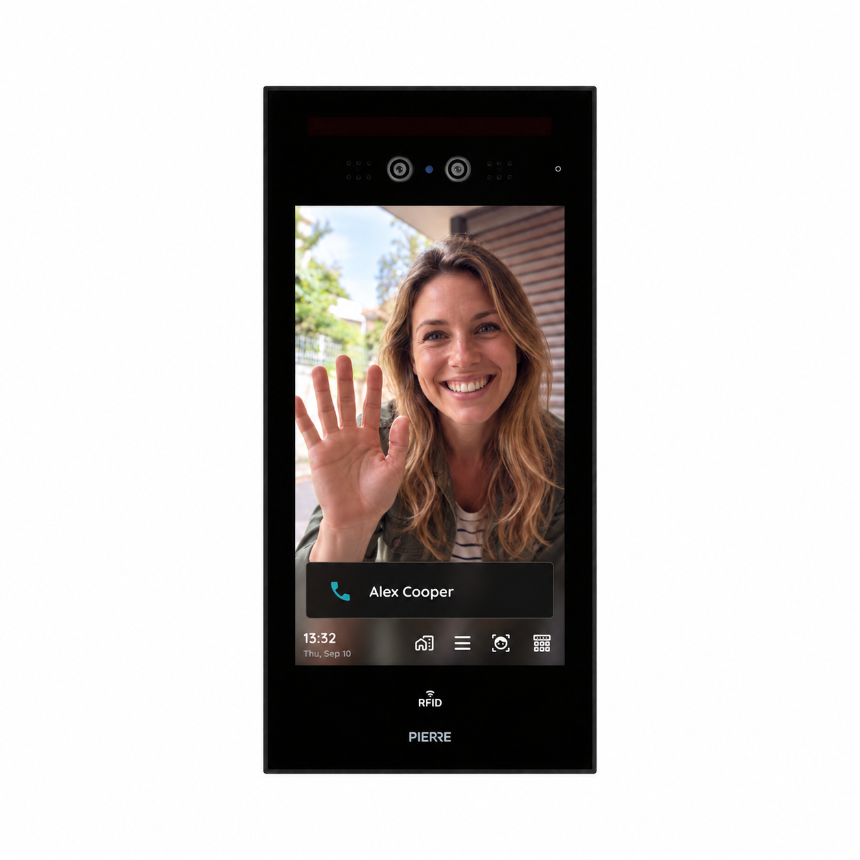
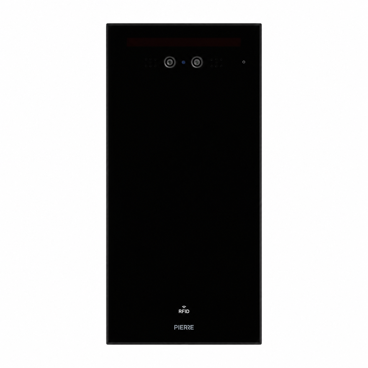
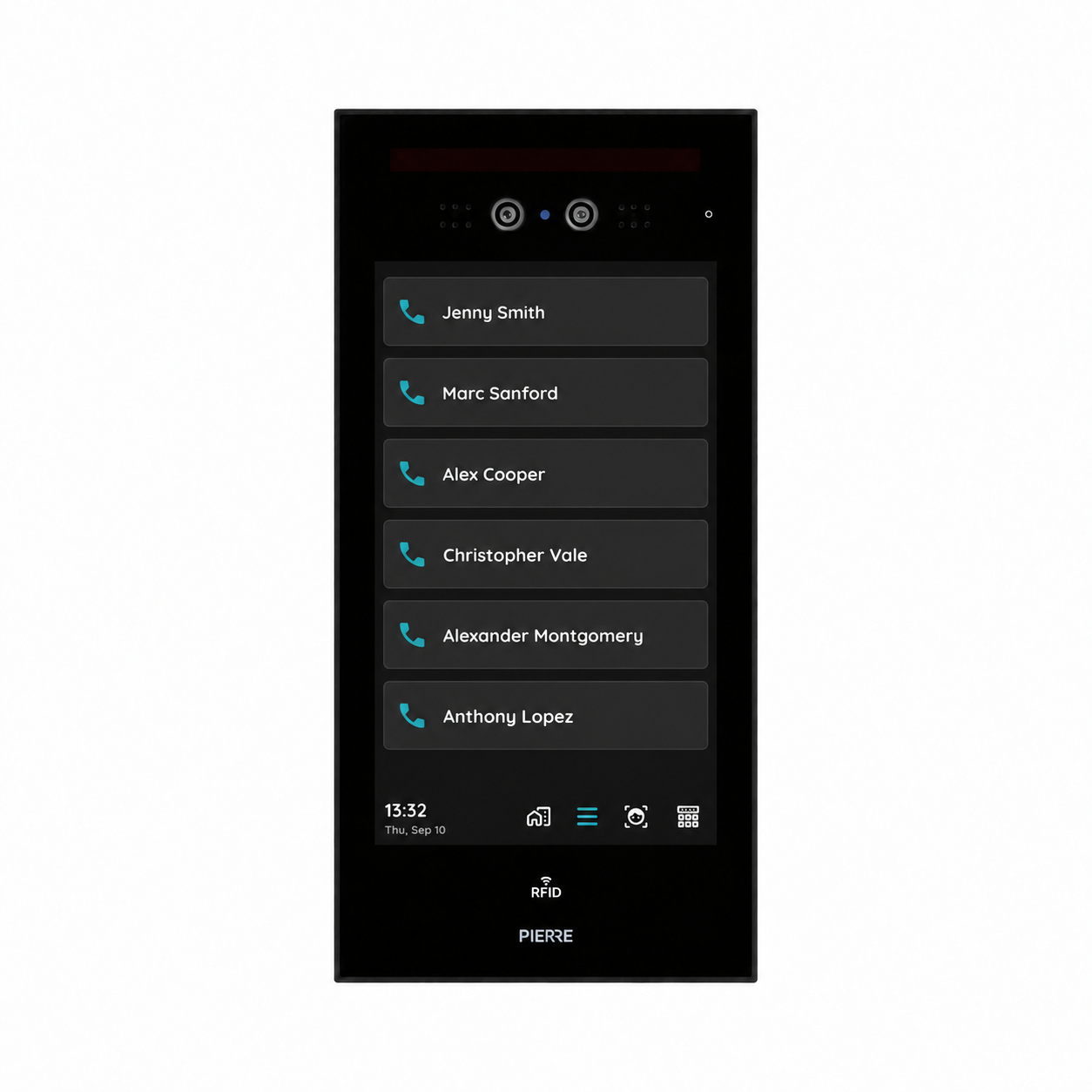
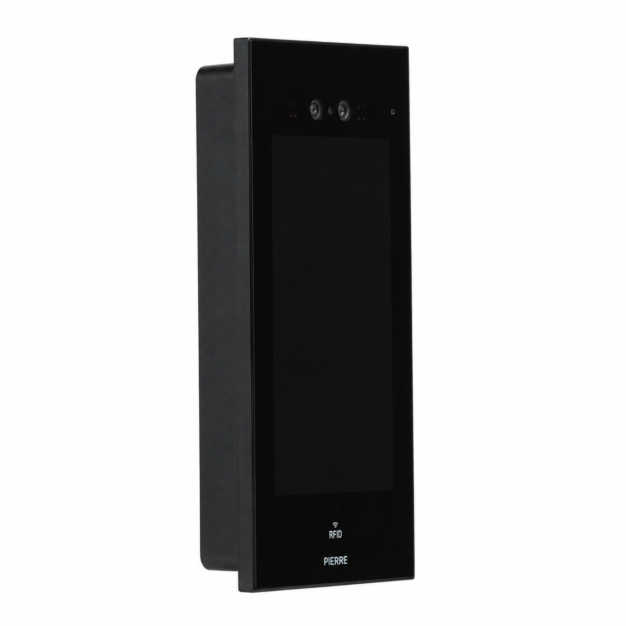
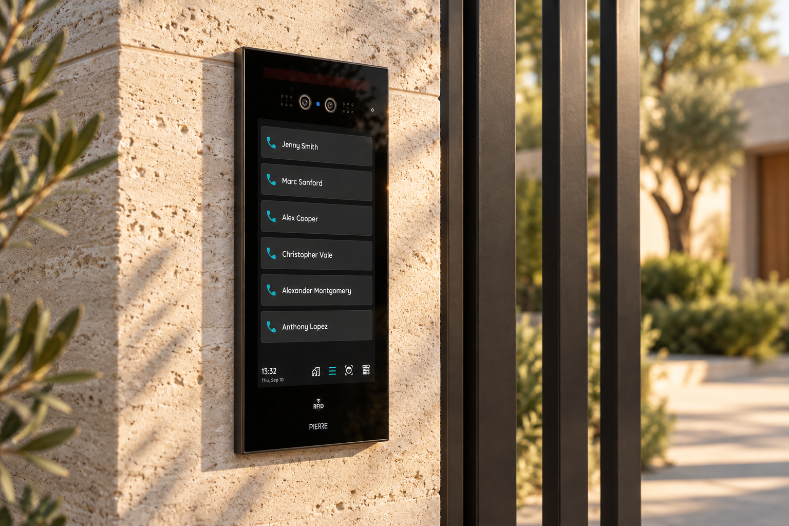
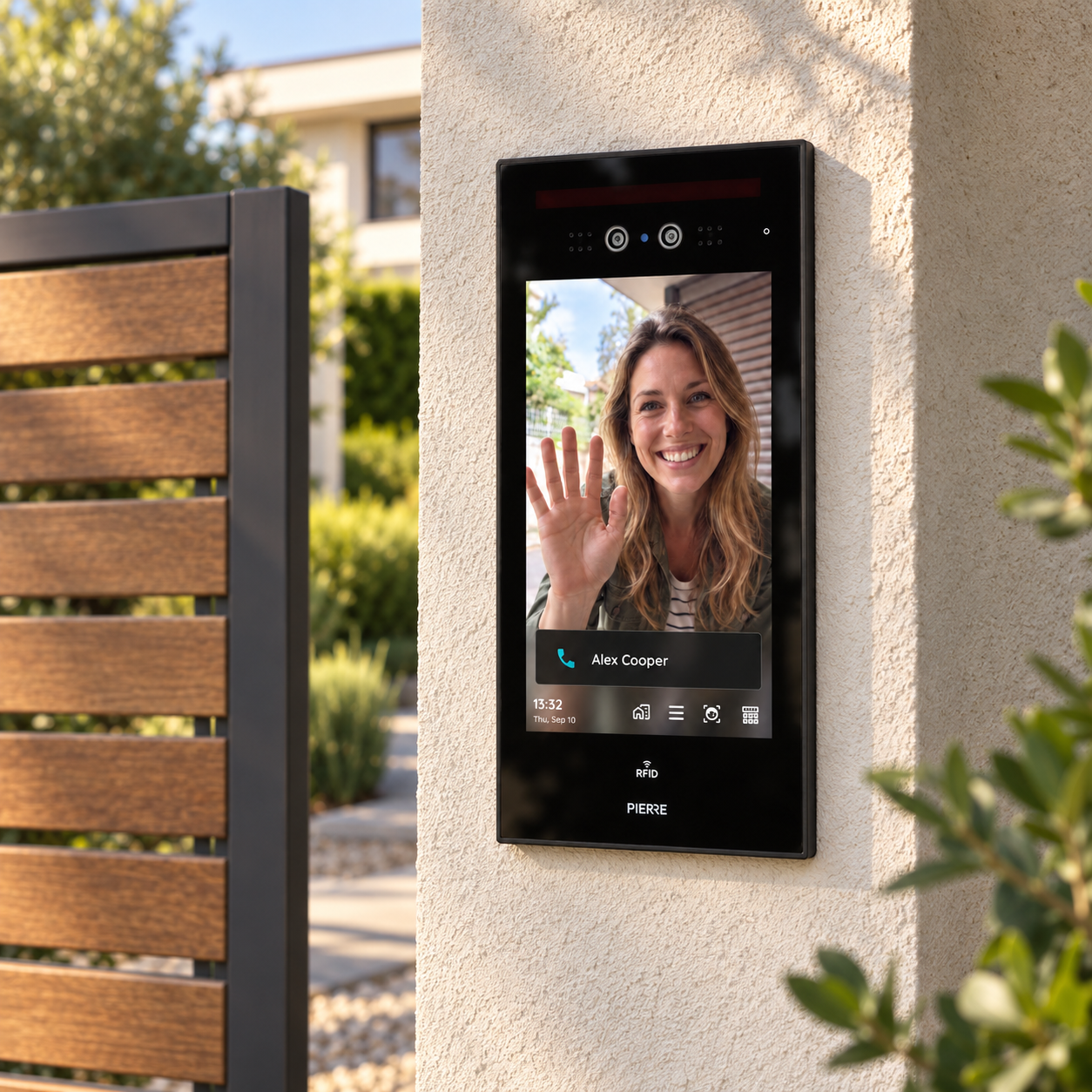
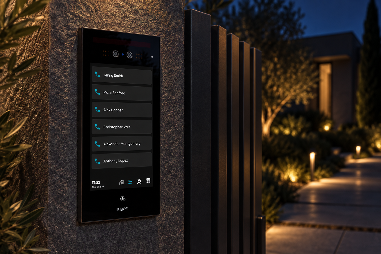
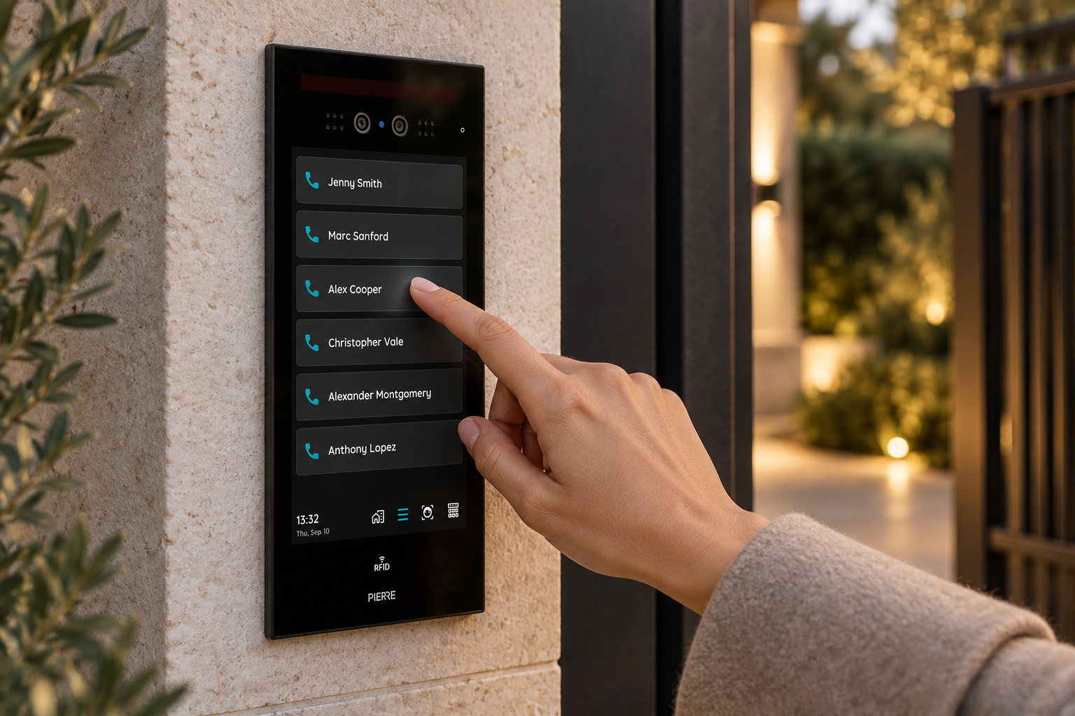
The PIERRE Intercom Denver 7" is a facial recognition IP outdoor panel for building entrances, featuring a 7-inch high-definition IPS touchscreen with a resolution of 1024 × 600 pixels. Visitors can call residents or the guard management centre directly from the panel.
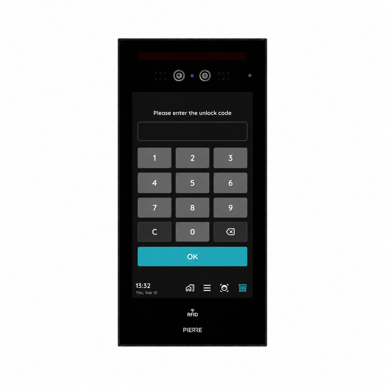
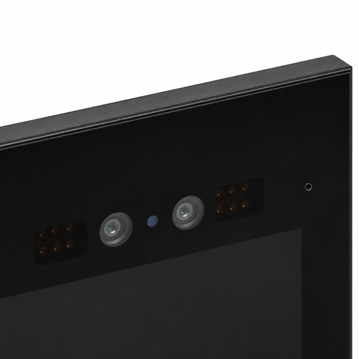
Dual 2-megapixel HD cameras – a colour camera and an infrared camera – with white LED supplementary lighting and a 115° × 90° viewing angle support reliable face recognition day and night. Doors can be opened by face, IC/ID card or PIN code, or remotely through the mobile app, which can also answer video calls.
Powered by a dual-core Cortex-A72 and quad-core Cortex-A53 processor running at 1.8 GHz, with 2 GB RAM and 8 GB storage, the panel runs Android. It connects via 10/100 Mbps RJ45 Ethernet and RS-485, and supports a Micro SD card.
A built-in microphone and loudspeaker with noise suppression and echo cancellation provide two-way audio. A relay output (COM/NO) controls the door lock, and alarm and door inputs support unlock detection.
The panel is powered via 12 V DC. Its tempered glass front panel, aluminium alloy body and sheet metal back shell are rated IP56 for outdoor use. It measures 117.8 × 232.2 × 8 mm and is designed for flush mounting, with an embedded size of 112 × 226 × 70 mm. The panel operates at temperatures from −25 °C to +70 °C and 10–93% relative humidity.
Key features
- 7-inch IPS touchscreen, 1024 × 600 pixels
- Dual 2 MP HD cameras (colour + infrared)
- Face recognition
- Unlock by face, IC/ID card, PIN code or mobile app
- Video calls answered via mobile app
- Dual-core Cortex-A72 + quad-core Cortex-A53, 1.8 GHz
- 2 GB RAM and 8 GB storage
- Android operating system
- RJ45 Ethernet (10/100 Mbps) and RS-485
- 12 V DC power supply
- Relay output (COM/NO) for door lock
- Noise suppression and echo cancellation
- Tempered glass panel, aluminium alloy body, IP56 rated
- Flush mounting
- Operating temperature: −25 °C to +70 °C
Technical specifications
| Camera | |
|---|---|
| Sensor Type | CMOS |
| Resolution | 2MP |
| Fill-in Light | White LED |
| View Angle | Horizontal 115°, Vertical 90° |
| Camera Features | Face recognition |
| Certification | |
| CE Marking | Yes |
| RoHS Compliant | Yes |
| Warranty | 2 years |
| Connectivity | |
| Interface | RJ45 |
| Connectivity | 10M/100M Ethernet RJ45, RS485 |
| Control | |
| Relay Type | Dry Contact None |
| Card Reader Technology | 125KHz / 13.56MHz |
| Access Modes | Smartphone, RFID Card, PIN |
| Display | |
| Touch Screen Dimension | 7 inch |
| Touch Screen Resolution | 1024x600px pixels |
| Electrical | |
| Power Supply | DC 12V |
| Environmental | |
| Operating Temperature | -25°C ~ +70°C |
| Operating Temperature (°C) | -25 ~ +70 |
| Operating Humidity | 10-93 % RH |
| IP Rating | IP56 |
| Hardware | |
| CPU | Dual-core Cortex-A72 + Quad-core Cortex-A53, 1.8GHz |
| Operating System | Android |
| OS Version | 11 |
| Memory (RAM) | 2 GB |
| Memory (ROM) | 8 GB |
| Physical | |
| Width | 117.8 mm |
| Height | 232.2 mm |
| Depth | 8 mm |
| Panel Material | Tempered glass |
| Material | Tempered glass panel + aluminum alloy body + sheet metal bottom shell |
| Product Color | Black |
| Mounting Type | Flush mount |
| Safety | |
| Safety Features | Door status detection |
Dimension drawings
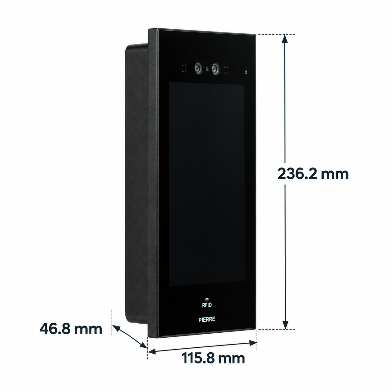
Physical & packaging
| Dimensions (L × W × H) | 8 × 117.8 × 232.2 mm |
|---|
User manual
- 1. Product Description
- 2. Technical specifications
- 3. Embedded installation guide
- 4. Lock Wiring Diagram – Fail-Secure Electric Locks
- 5. Lock Wiring Diagram – Fail-Safe Locks
- 6. Modbus RTU (RS485) Wiring Instructions
- 7. Add the Intercom in the PIERRE App
- 8. Access and Tokens
- 9. Intercom Settings in the PIERRE App
1. Product Description
The PIERRE Intercom Denver 7″ is a smart IP outdoor intercom designed for secure and convenient building access. Featuring a 7-inch HD touchscreen and dual cameras with infrared technology, it provides reliable facial recognition both day and night.
The system supports multiple access methods, including facial recognition, IC/ID card, PIN code, and remote unlocking via the mobile app. Residents can receive video calls, communicate with visitors, and unlock doors remotely.
With its advanced facial recognition technology and wide-angle cameras, the Denver 7″ is ideal for residential and commercial buildings. It offers two-way audio with noise cancellation, Ethernet connectivity, and secure door access control.
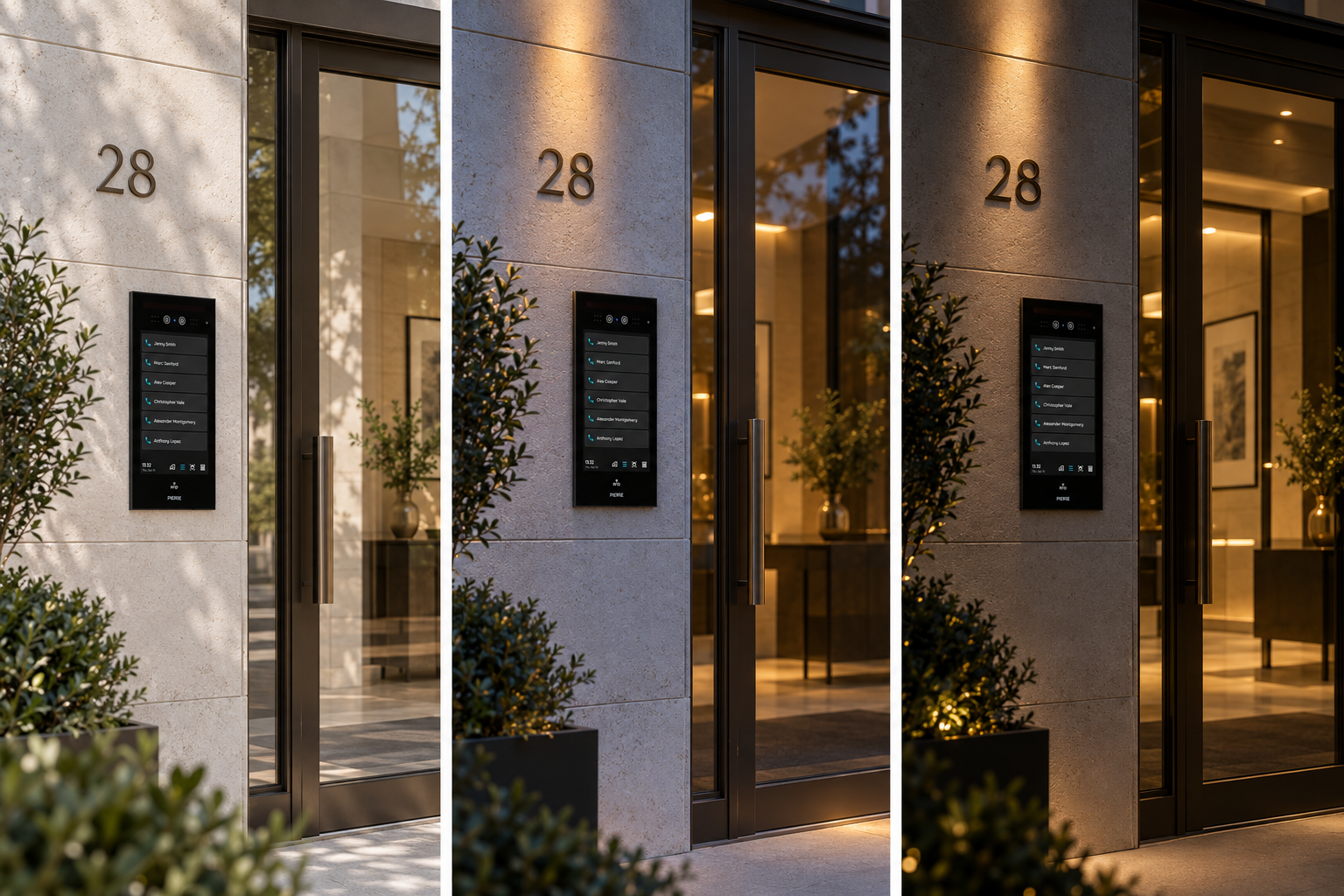
Its durable IP56-rated aluminium and tempered glass housing ensures reliable outdoor operation, while the flush-mounted design provides a clean, modern appearance.
2. Technical specifications
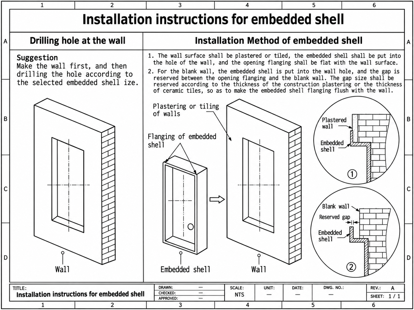
3. Embedded installation guide
4. Lock Wiring Diagram – Fail-Secure Electric Locks
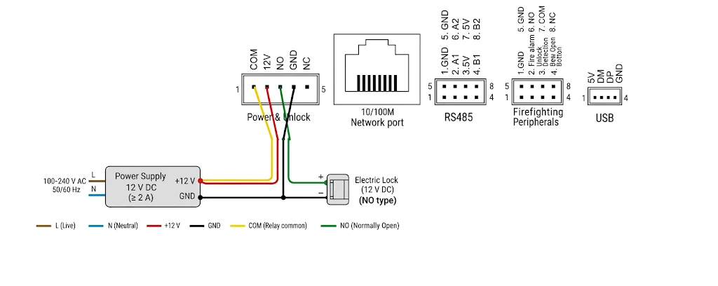
This wiring configuration is designed for 12V DC Fail-Secure electric locks, using the intercom's NO (Normally Open) and COM (Common) relay contacts.
How Fail-Secure Locks Work
- NO (Normally Open): Relay contact used to activate the lock.
- COM (Common): Common relay contact.
- Without power: The lock remains locked.
- When activated: The intercom connects NO to COM, supplying power to unlock the door.
- Typical application: Fail-secure electric strikes.
Wiring Instructions – NO Electric Lock (12V DC)
- Power Supply: Connect the 100–240V AC mains (L and N) to the 12V DC power supply.
- Intercom Power: Connect +12V (red) and GND (black) from the power supply to the corresponding intercom terminals.
- COM Connection: Connect the power supply's +12V to the intercom's COM terminal (yellow).
- NO Connection: Connect the intercom's NO terminal (green) to the electric lock's positive (+) terminal.
- Lock GND: Connect the electric lock's negative (−) terminal to the power supply's GND (black).
Operation
When the unlock button is pressed, the intercom relay connects COM to NO, supplying 12V DC to the electric lock and releasing the door.
When the relay returns to its normal state, power to the lock is interrupted, and the lock returns to its locked state.
Important Notes
- Power Supply Selection: Always check the combined current consumption (amperage) of the intercom and electric lock before selecting a power supply. The power supply must provide sufficient current to operate both devices simultaneously, with additional capacity for peak loads.
- Voltage Compatibility: Ensure that both the intercom and electric lock are compatible with the 12V DC power supply.
- Relay Rating: Verify that the electric lock's current consumption does not exceed the intercom relay's maximum rated current.
5. Lock Wiring Diagram – Fail-Safe Locks
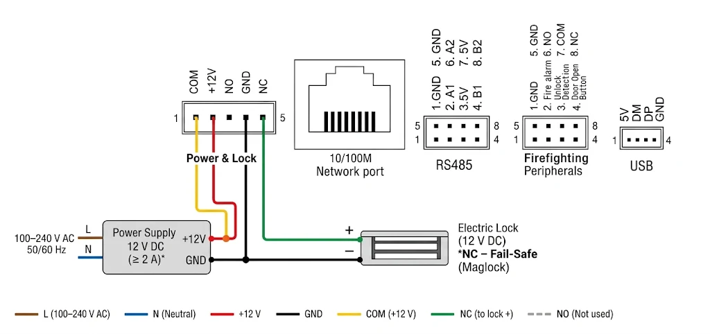
Fail-Safe Lock → NC + COM
- NC (Normally Closed): The relay contact is closed when the intercom relay is inactive.
- COM (Common): The common terminal of the intercom relay.
- The lock stays LOCKED while power is supplied.
- When the intercom activates the relay, NC disconnects from COM, cutting power to the lock and allowing it to unlock.
- Commonly used with fail-safe electromagnetic locks (maglocks).
Wiring Instructions – NC Electric Lock (12V DC)
- Power Supply: Connect the 100–240V AC mains (L and N) to the 12V DC power supply.
- Intercom Power: Connect +12V (red) and GND (black) from the power supply to the corresponding intercom terminals.
- COM Connection: Connect +12V (yellow) from the power supply to the COM terminal of the intercom.
- NC Connection: Connect the NC terminal of the intercom to the positive (+) terminal of the electric lock.
- Lock Ground: Connect the negative (−) terminal of the electric lock to the GND of the power supply.
- NO Terminal: Not used.
Important Notes
- Power Supply: Always check the combined maximum current consumption of the intercom and electric lock before selecting a power supply. Ensure it provides sufficient current for both devices, with an appropriate safety margin.
- Fail-Safe Operation: The lock automatically unlocks when power is lost.
- Compatibility: Verify that the intercom supports NC relay operation for unlocking.
- Safety: For emergency exits, ensure the installation complies with applicable fire safety regulations and provides the required emergency release mechanism.
6. Modbus RTU (RS485) Wiring Instructions
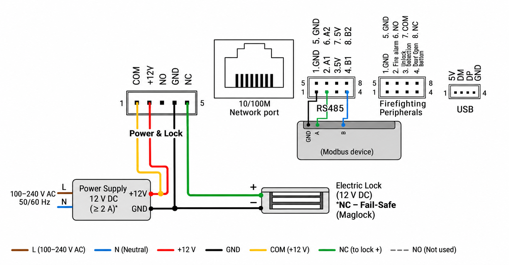
The intercom provides A and B terminals for RS485 communication, which can be used for Modbus RTU if supported by the device firmware.
Wiring Instructions – Modbus RS485
- A Connection: Connect the intercom's A terminal (green) to the RS485 A terminal of the Modbus device.
- B Connection: Connect the intercom's B terminal (blue) to the RS485 B terminal of the Modbus device.
- GND Connection: Connect the intercom's GND terminal (black) to the Modbus device's signal GND, if required.
- +5V Terminal: Leave the +5V terminal disconnected. It is not required for RS485 communication.
- Cable: Use a twisted-pair cable for A and B to minimize electrical interference.
Important Notes
- Polarity: Verify the A/B terminal designations on both devices, as manufacturers may use different conventions.
- Termination: Install 120Ω termination resistors at both physical ends of the RS485 bus when required.
- Communication Settings: Ensure both devices use compatible baud rate, parity, stop bits, and Modbus configuration.
- Protocol Compatibility: Confirm that the intercom firmware supports Modbus RTU. RS485 hardware support alone does not guarantee Modbus compatibility.
7. Add the Intercom in the PIERRE App
When the intercom is powered on, its screen shows a QR code. Scan this code with the PIERRE app to add the intercom to a building.
First select the building you want to add the intercom to, then follow the steps below.
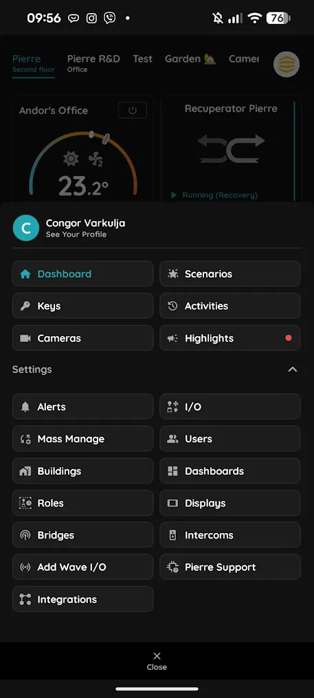
Step 1 – Open the settings
Open the Menu and go to Settings.
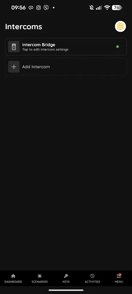
Step 2 – Open Intercoms
Tap Intercoms. The list shows the intercoms already added to the building.
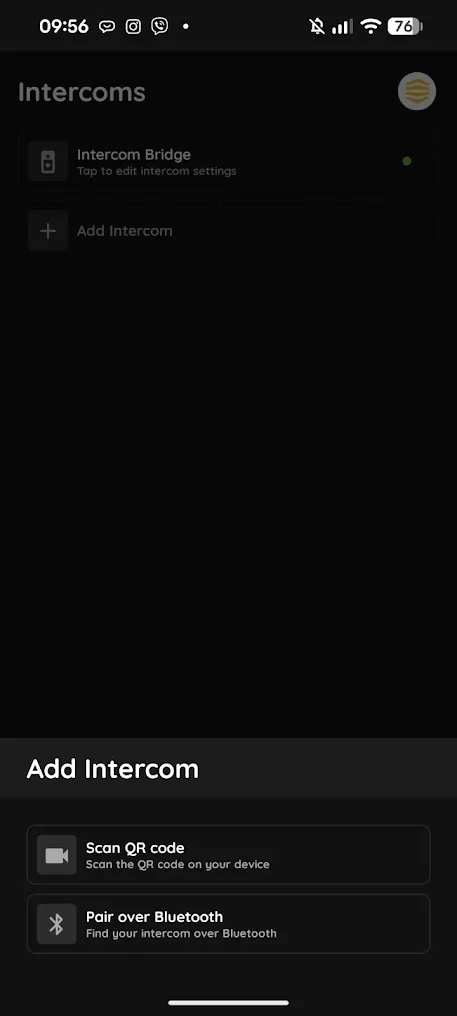
Step 3 – Add the intercom
Tap Add Intercom, then choose Scan QR code.
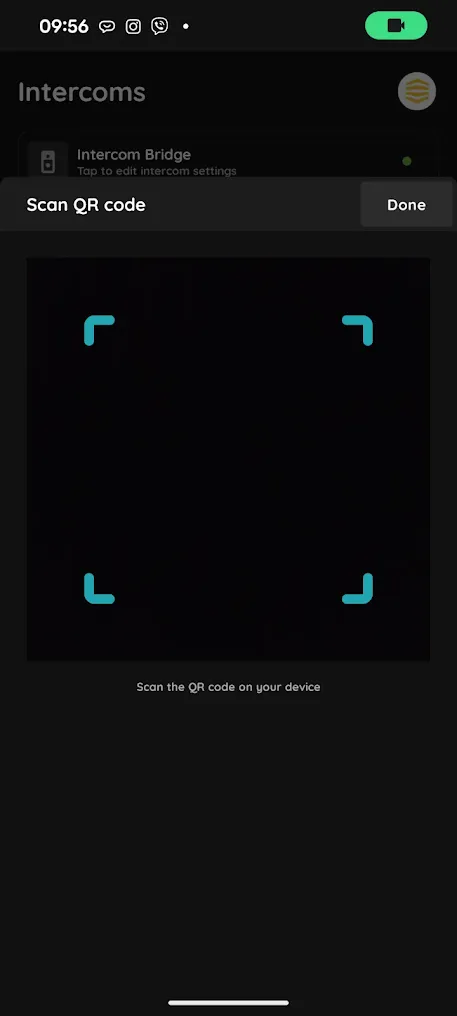
Step 4 – Scan the QR code
Point the phone's camera at the QR code on the intercom's screen.
Automatic setup: make sure the intercom is added to the right building – the main building or the correct sub-building. The intercom then automatically finds all displays and users added to that building, so no further programming is needed.
8. Access and Tokens
All access to the intercom is managed in the PIERRE app with PIERRE tokens. Face recognition, PIN codes and RFID cards are added as tokens, so nothing has to be enrolled directly on the intercom. Every user with access to the building adds their own tokens from their profile.
If a door is connected to the intercom, it also appears in the PIERRE app as a door I/O, so it can be opened from the app as well.
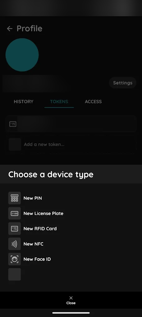
Add a token
- Open the Menu and tap your name (See Your Profile).
- Open the TOKENS tab.
- Tap Add a new token… and choose the token type.
- Enter a Name for the token and complete the steps for that type.
Token types
- New PIN: enter a code of 6–16 digits. Simple codes, such as repeated digits, are refused as too weak.
- New RFID Card: enter the card number, or on Android hold the card to the phone to read it.
- New Face ID: the phone's front camera takes three photos – front, left side and right side. Photos without a clearly visible face are rejected.
- New License Plate: for licence plate recognition; not used by the intercom.
Which doors a token opens
A token does not select doors itself. It opens the doors that the user's roles give access to, on the days and at the times set for those roles. Roles and time limits are shown on the ACCESS tab of the profile.
Administrators can also add tokens for other users from that user's profile, on the TOKENS tab.
9. Intercom Settings in the PIERRE App
Open Menu → Settings → Intercoms and tap the intercom to open its settings. The settings are grouped in tabs: Info, Screens, Network, Face Rec., Calls, Contacts, Settings, IOs and Doors. Change a tab, then tap Submit or Done to save.
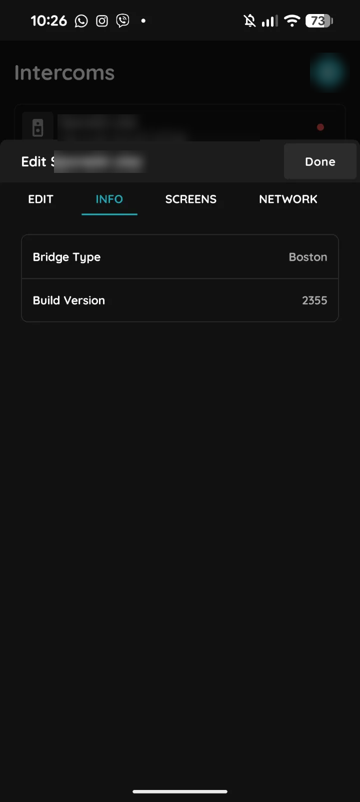
Info
Shows the intercom type and the firmware build installed on it.
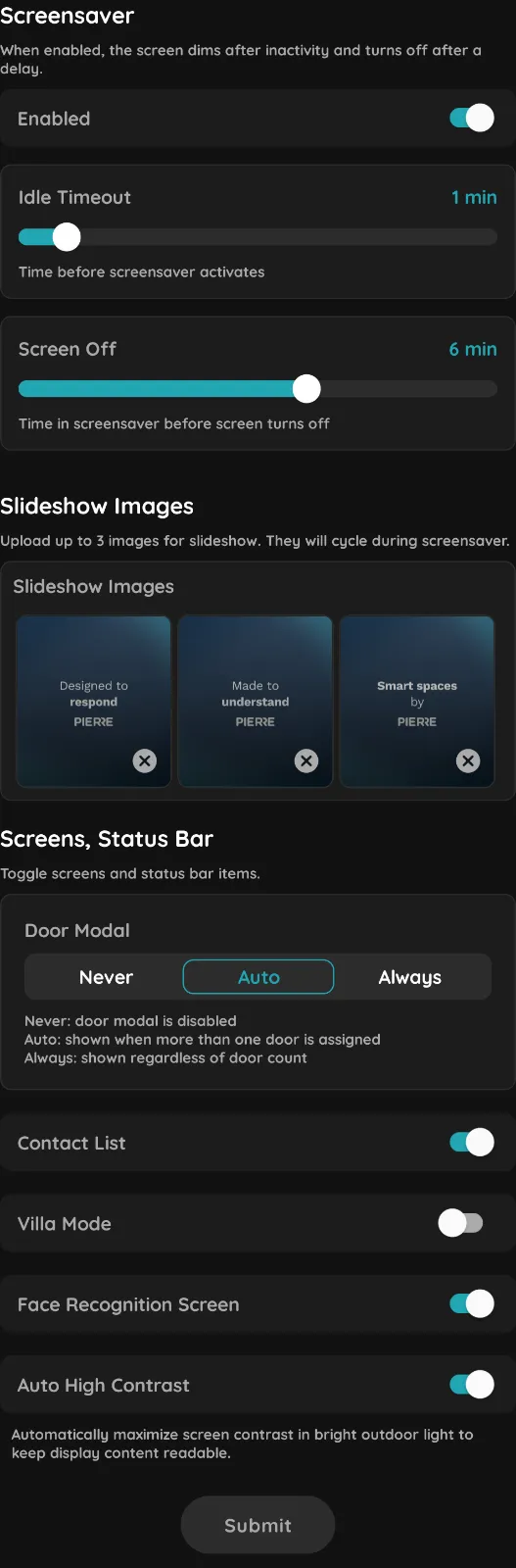
Screens
- Screensaver: turn it on or off. Idle Timeout sets how long the intercom waits before the screensaver starts; Screen Off sets how long the screensaver runs before the screen turns off.
- Slideshow Images: upload up to 3 images that cycle during the screensaver.
- Door Modal: when the door window appears on the intercom. Never turns it off, Auto shows it only when more than one door is assigned, Always shows it regardless of the number of doors.
- Contact List, Villa Mode and Face Recognition Screen: show or hide these screens on the intercom.
- Auto High Contrast: raises the screen contrast in bright outdoor light so the display stays readable.
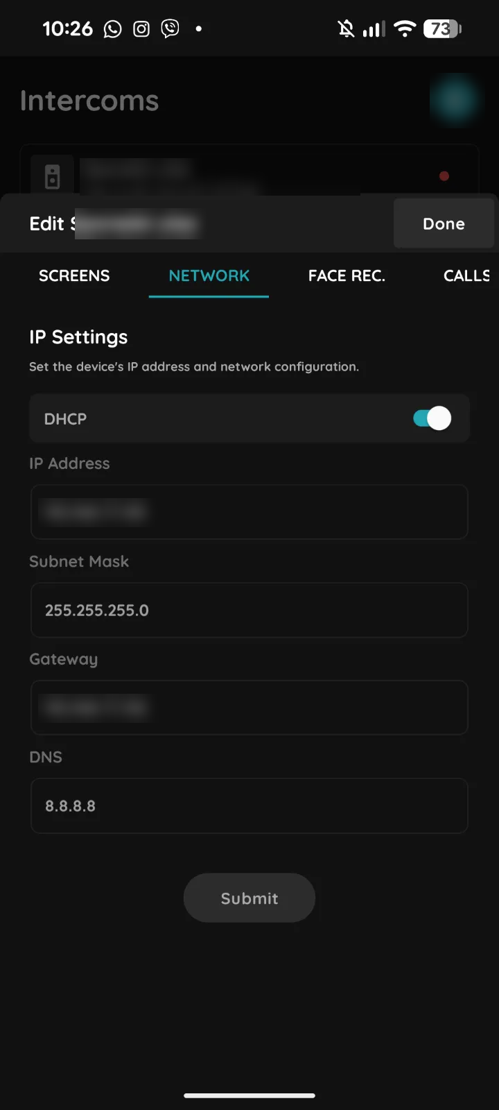
Network
Sets the intercom's IP address. With DHCP on, the router assigns the address. Turn DHCP off to enter the IP Address, Subnet Mask, Gateway and DNS yourself. Tap Submit to save.
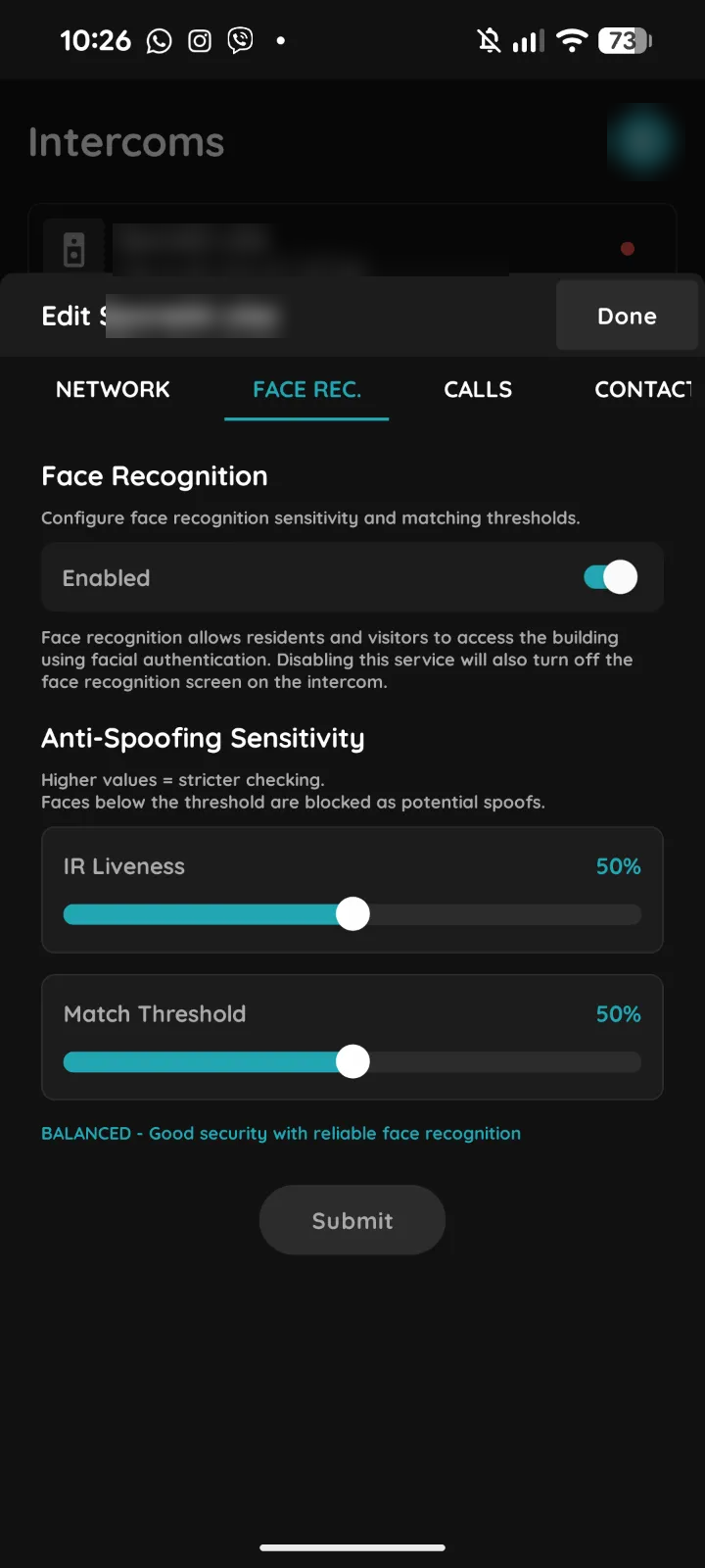
Face recognition
- Enabled: lets residents and visitors open the door with their face. Turning it off also hides the face recognition screen on the intercom.
- IR Liveness and Match Threshold: how strictly a face is checked. Higher values are stricter; faces below the threshold are blocked as possible spoofs. The line below the sliders shows the resulting level, for example Balanced.
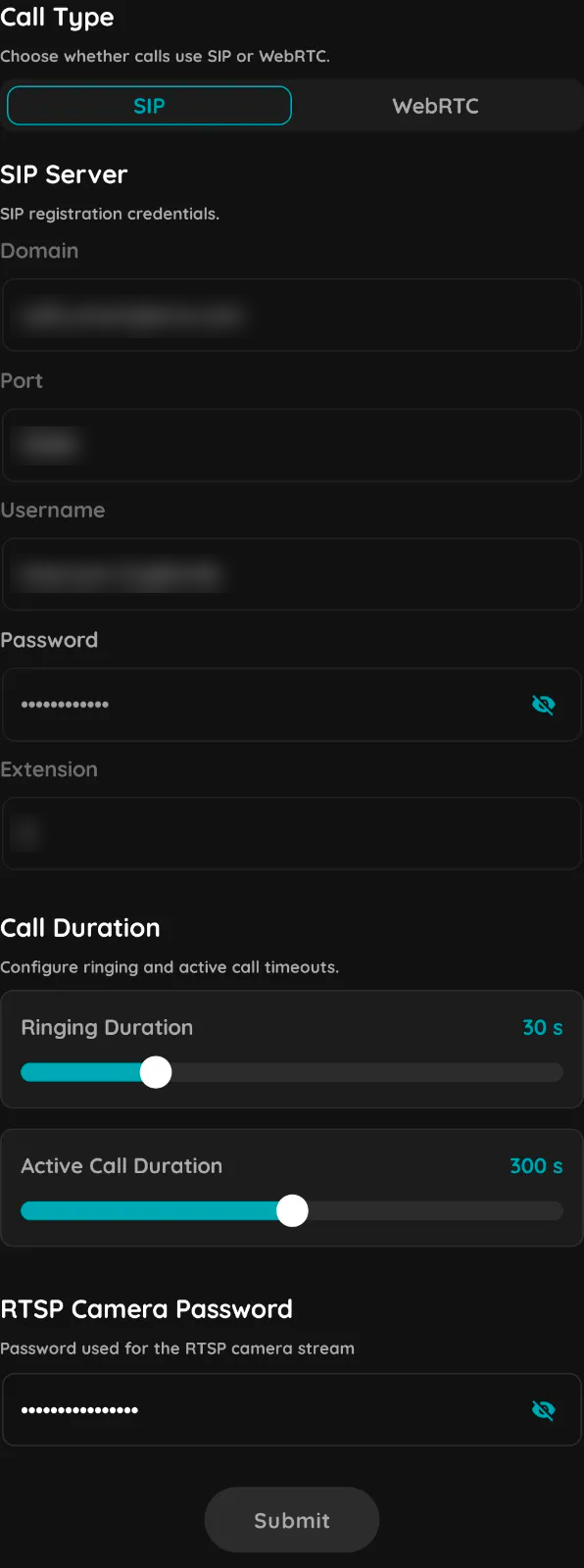
Calls
- Call Type: whether calls use SIP or WebRTC.
- SIP Server: the SIP registration details – Domain, Port, Username, Password and Extension.
- Call Duration: Ringing Duration is how long a call rings; Active Call Duration is how long an answered call can last.
- RTSP Camera Password: the password for the intercom camera's RTSP stream.
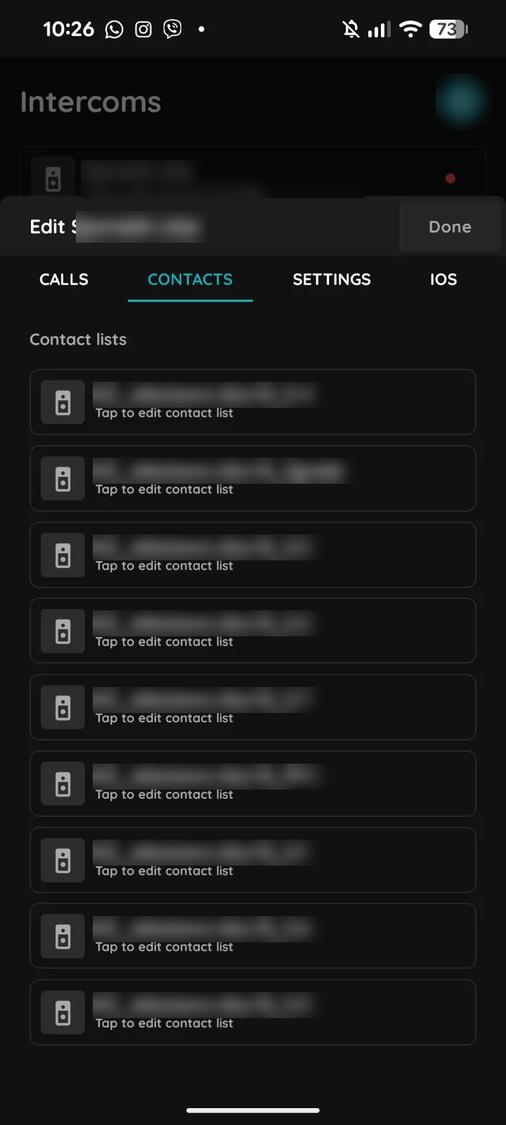
Contacts
Lists the contact lists on the intercom. Tap a list to edit it.
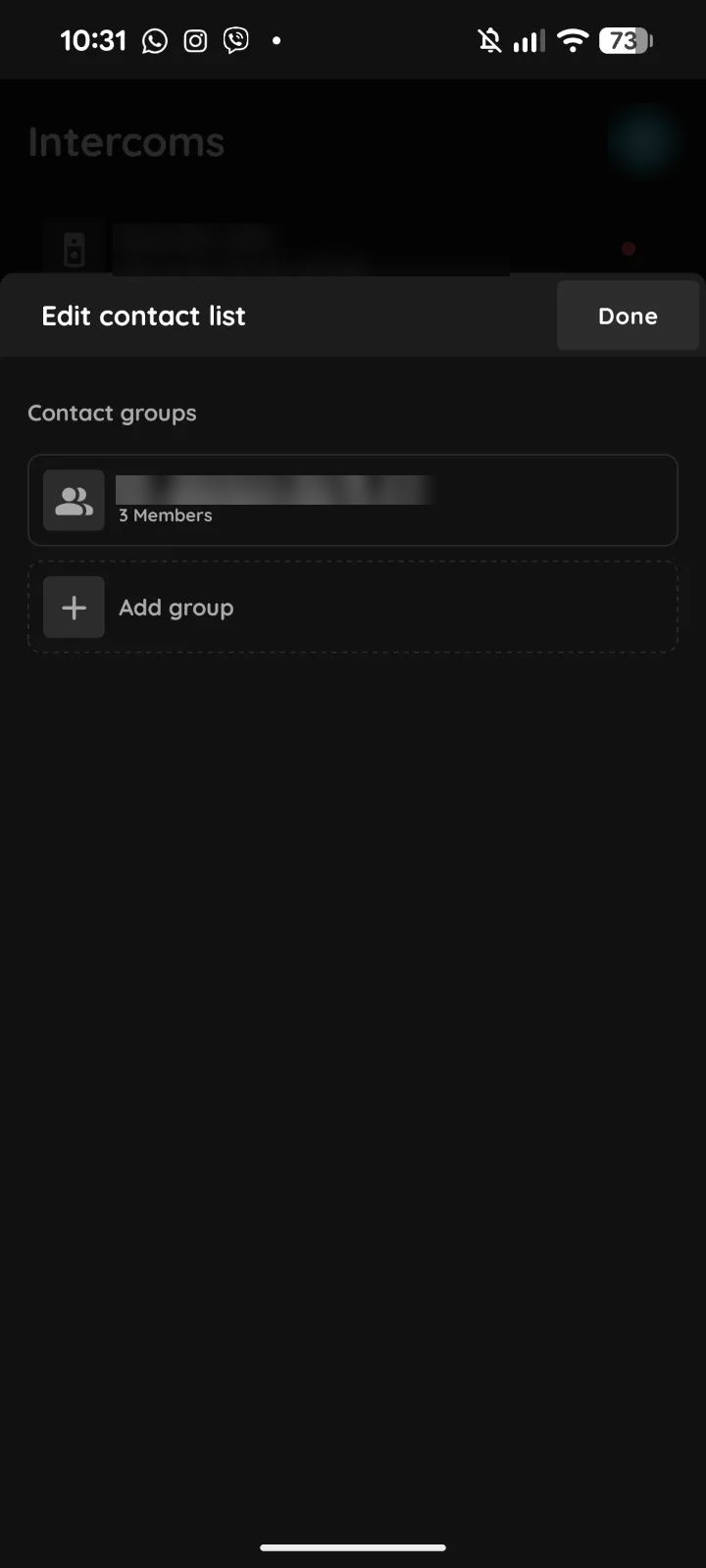
Contacts – contact list
Shows the contact groups in the list and how many members each has. Tap a group to edit it, or tap Add group to create one.
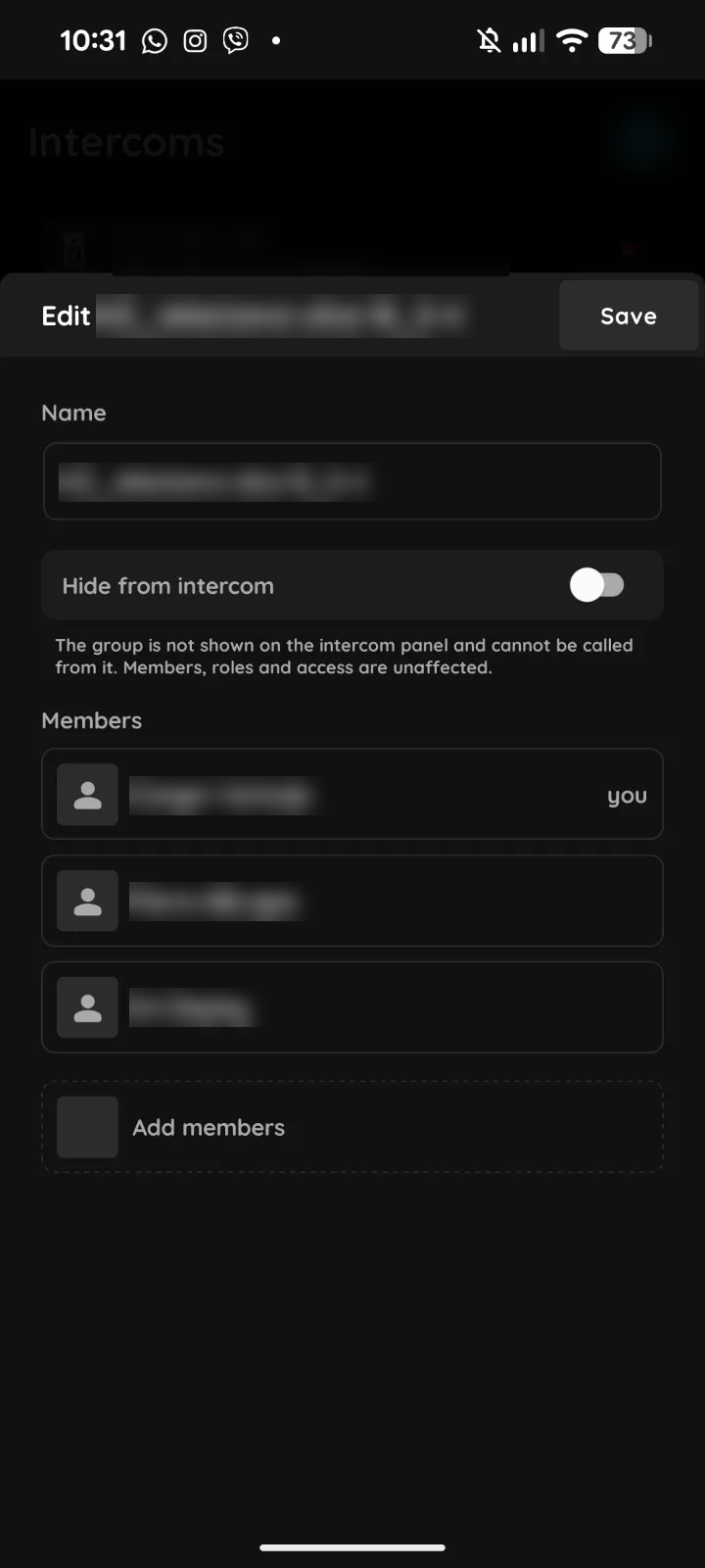
Contacts – group members
- Name: the group name shown on the intercom.
- Hide from intercom: the group is not shown on the intercom panel and cannot be called from it. Members, roles and access are not affected.
- Members: the users who receive calls for this group. Tap Add members to add more, then Save.
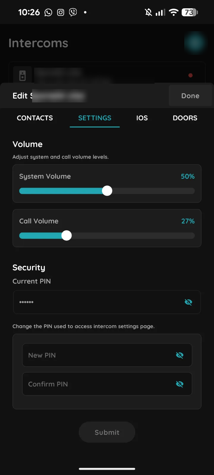
Settings
- Volume: System Volume and Call Volume of the intercom.
- Security: change the PIN that protects the intercom's settings page. Enter the current PIN, then the new PIN twice, and tap Submit.
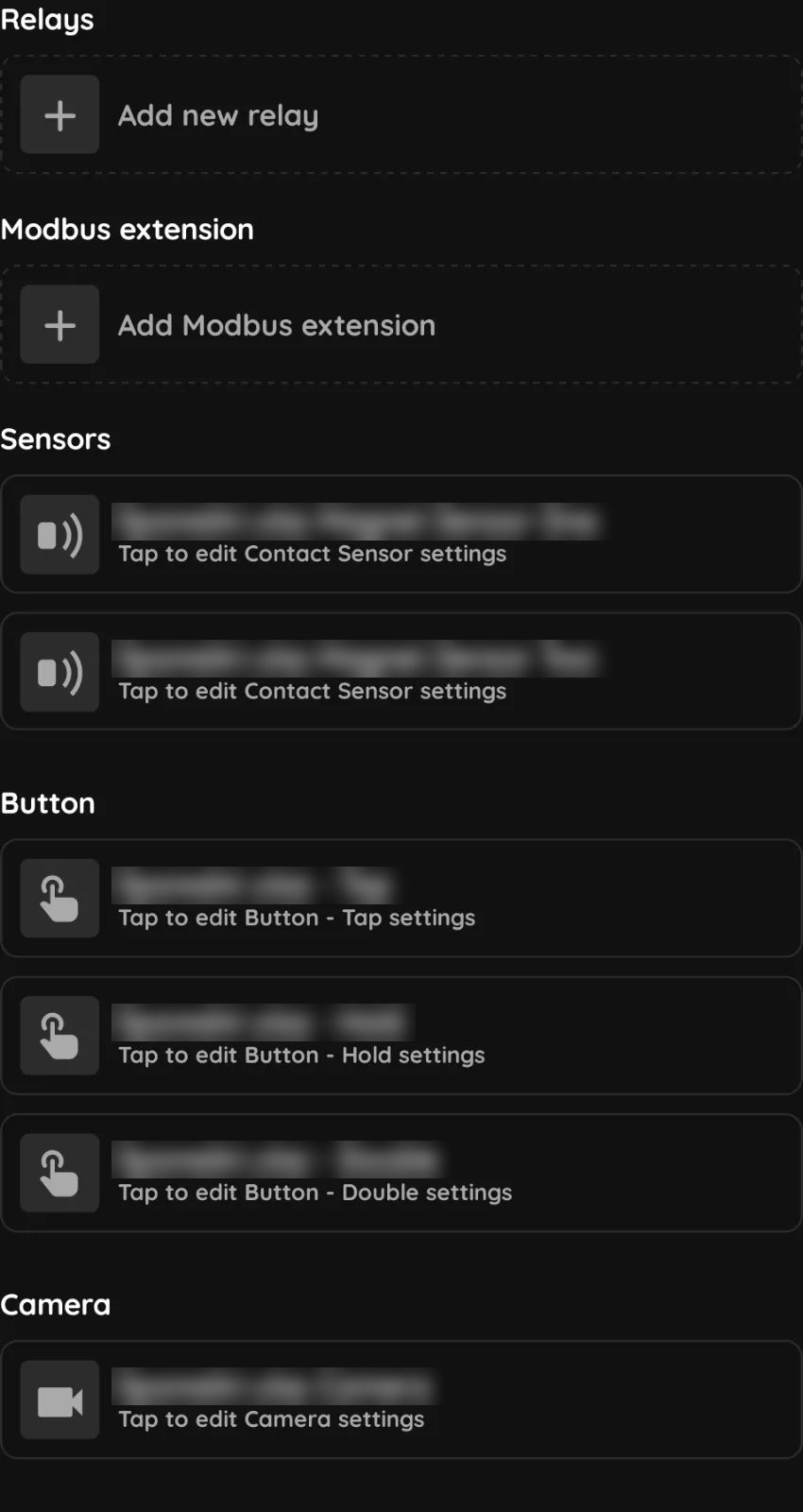
IOs
- Relays: add a relay output.
- Modbus extension: add a Modbus device connected to the intercom.
- Sensors: the intercom's contact (magnet) sensor inputs. Tap one to edit it.
- Button: the intercom button, with separate settings for a tap, a hold and a double press.
- Camera: the intercom's camera settings.
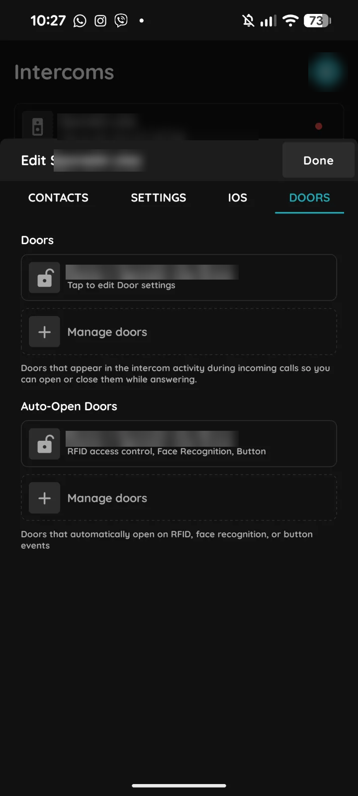
Doors
- Doors: the doors shown on an incoming call, so you can open or close them while answering. Tap Manage doors to change them.
- Auto-Open Doors: doors that open automatically on an RFID card, face recognition or button event.