
PIERRE PRO Controller
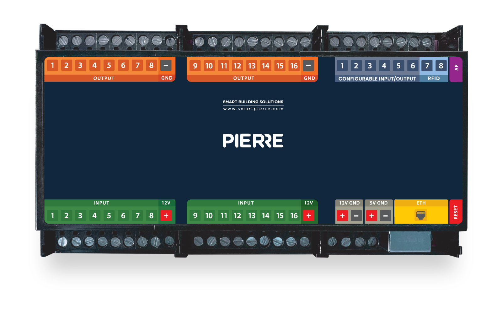
| SKU | PP-C-PRO |
|---|---|
| Product line | PIERRE Pro |
| Category | Controllers |
| Manufacturer | JLCPCB |
| GTIN / EAN | 8606034720048 |
| HS code | 8537109100 |
Overview
The PIERRE Controller PRO is engineered for smart home automation, providing enhanced capabilities for managing connected systems. With a 12V DC input and a power consumption of 1.5 W, it is designed for efficient energy usage. The controller offers dual output voltages of 12V DC and 5V DC, with each output capable of handling a maximum load of 1A, ensuring compatibility with a variety of devices.
This model features flexible integration into existing systems and enabling effective remote management. It is optimized to perform reliably across a range of temperature and humidity conditions, suitable for diverse applications, including those at elevated altitudes.
Incorporating safety features such as reverse polarity protection and overvoltage protection ensures the unit's durability and operational reliability. The PIERRE Controller PRO is a robust solution and has a reliable control over smart home systems.
Key features
12V DC input, 1.5W consumption, dual output voltages 12V DC and 5V DC, maximum load per output: 1A, overvoltage protection 12V DC - 15V DC, reverse polarity protection
Technical specifications
| Certification | |
|---|---|
| CE Marking | Yes |
| Electrical | |
| Power Supply | DC 12V 1A |
| Input Voltage | DC 12 V |
| Input/Output Count | 16+16 |
| Power Consumption | 1.5 W |
| Current | 0.10 A |
| Max Load per Output | 1A |
| Max Load | 2A |
| Over Voltage Range | 12V DC - 15V DC |
| Environmental | |
| Operating Temperature | +32°F - +131°F |
| Operating Temperature (°C) | 0 - +55 |
| Operating Humidity | 5% - 90% RH Non-condensing % RH |
| Altitude | <3000m |
| Features | |
| LED Indicators | Yes |
| Physical | |
| Panel Material | ABS+PC material |
| Product Color | Black |
| Mounting Type | DIN Rail |
| Connectivity | |
| Connectivity | 10M/100M Ethernet RJ45, 2.4GHz Wi-Fi (802.11 b/g/n), Modbus |
| Safety | |
| Safety Features | Over voltage protection, Reverse polarity protection |
Electrical & I/O
| Operating voltage | 24 V |
|---|---|
| Power consumption | 48 W |
| Max. current | 2 A |
| Recommended circuit breaker | 6 A |
| Connection | DC+/DC- |
| Requires neutral | Yes |
| Requires ground | Yes |
| DIN rail | 9 module(s) |
Pin layout
| Pin | Label | Type | Position |
|---|---|---|---|
| 1 | Out1 | digital_output | top |
| 2 | Out2 | digital_output | top |
| 3 | Out3 | digital_output | top |
| 4 | Out4 | digital_output | top |
| 5 | Out5 | digital_output | top |
| 6 | Out6 | digital_output | top |
| 7 | Out7 | digital_output | top |
| 8 | Out8 | digital_output | top |
| 9 | GND OUT | power_gnd_out | top |
| 10 | Out9 | digital_output | top |
| 11 | Out10 | digital_output | top |
| 12 | Out11 | digital_output | top |
| 13 | Out12 | digital_output | top |
| 14 | Out13 | digital_output | top |
| 15 | Out14 | digital_output | top |
| 16 | Out15 | digital_output | top |
| 17 | Out16 | digital_output | top |
| 18 | GND OUT | power_gnd_out | top |
| 19 | CFG1 | configurable_io | top |
| 20 | CFG2 | configurable_io | top |
| 21 | CFG3 | configurable_io | top |
| 22 | CFG4 | configurable_io | top |
| 23 | CFG5 | configurable_io | top |
| 24 | CFG6 | configurable_io | top |
| 25 | CFG7 | input_only | top |
| 26 | CFG8 | input_only | top |
| 27 | Input1 | digital_input | bottom |
| 28 | Input2 | digital_input | bottom |
| 29 | Input3 | digital_input | bottom |
| 30 | Input4 | digital_input | bottom |
| 31 | Input5 | digital_input | bottom |
| 32 | Input6 | digital_input | bottom |
| 33 | Input7 | digital_input | bottom |
| 34 | Input8 | digital_input | bottom |
| 35 | 12V+ OUT | output_12v_plus | bottom |
| 36 | Input9 | digital_input | bottom |
| 37 | Input10 | digital_input | bottom |
| 38 | Input11 | digital_input | bottom |
| 39 | Input12 | digital_input | bottom |
| 40 | Input13 | digital_input | bottom |
| 41 | Input14 | digital_input | bottom |
| 42 | Input15 | digital_input | bottom |
| 43 | Input16 | digital_input | bottom |
| 44 | 12V+ OUT | output_12v_plus | bottom |
| 45 | 12V+ IN | power_12V_input | bottom |
| 46 | 12V GND IN | power_gnd_in | bottom |
| 47 | 5V+ OUT | output_5v_plus | bottom |
| 48 | 5V GND | 5v_gnd_out | bottom |
| 49 | ETH | ethernet_in | bottom |
Physical & packaging
| Dimensions (L × W × H) | 156 × 31 × 89 mm |
|---|---|
| Weight | 213 g |
| Box dimensions (L × W × H) | 170 × 30 × 100 mm |
| Box weight | 250 g |
User manual
- 1. Product Size
- 2. Wiring
- 3. Product Description
- 4. Controller Color Status
- 5. Commissioning Process
- 6. Controller Setup Options
- 7. Existing Controller in Commissioning Mode
- 8. Product specifications
1. Product Size
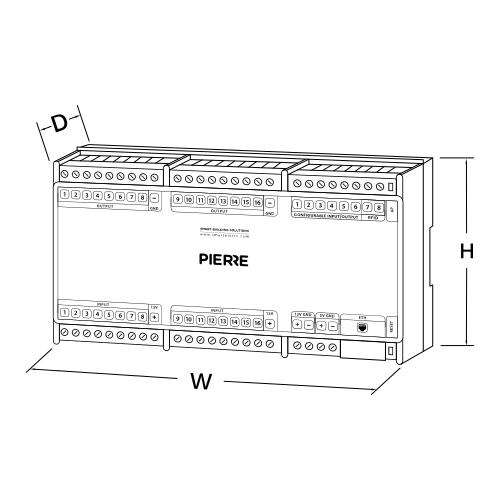
W: 156 mm
H: 89 mm
D: 31 mm
2. Wiring
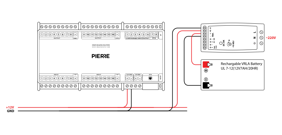
Wiring the Controller to a Big Power Supply
- Connect L and N terminals of the power supply to the AC mains (Live and Neutral).
- The DC output provides +12 V and GND, which power the Controller.
- A rechargeable 12 V VRLA battery is connected to the Bat.+ and Bat.− terminals of the power supply; observe the polarity.
- This allows the battery to charge while mains power is available, and supply backup power during outages.
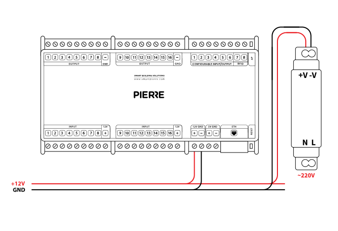
Wiring the Controller to a smaller Power Supply
- Connect the AC input terminals to mains power: L (Live) and N (Neutral).
- The power supply converts AC to 12 V DC, with outputs labelled +V and −V.
- Connect +V to the Controller’s 12 V + terminal and −V to its 12 V GND terminal.
- Use proper gauge wires and double-check polarity to avoid damaging connected devices.
3. Product Description
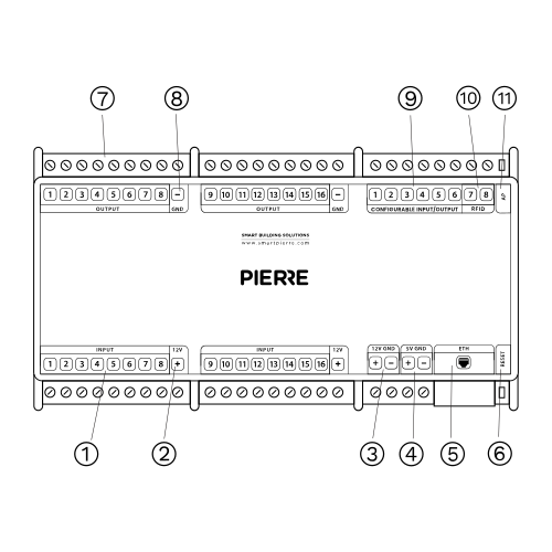
Description of the PINs on the Controller:
- INPUT from 1 to 16 ports - INPUT for sensor wires and buttons
- Power supply for the sensor
- PLUS - MINUS connection to a voltage of 12 V
- PLUS - MINUS connection to a voltage of 5 V
- ETH: Connecting to the network
- Reset button
- OUTPUT - from 1 to 16 ports: OUTPUT to wire the corresponding actuator device that will activate when it receives input from the sensors, buttons, smartphone, display or automation.
- GRD - Ground wire (-)
- A combination of digital inputs or outputs
- Digital input - 2 ports used only for RFID communication (Wiegand 34bit)
- AP - access point - It is a working mode used for the initial setup of the controller and for modifying configuration settings later while the controller is in operation.
- LED - indicator of network connection-It provides essential information about the controller’s current status, making it easy to monitor its connection, operation mode, and maintenance activities.
GOOD TO KNOW: If one Input has influence on the Output they both should be added to the same Controller. For example in situation when RFID reader opens the door, they should be add to the same Controller for best performances.
4. Controller Color Status
The colors that shows different statuses of the Controller:
- Green – Online:
- The controller is online and connected to the network, functioning as expected.
- Red – Offline:
- The controller is offline, indicating a disconnection from the network or that there is no internet access.
- Light Blue – AP Mode:
- The controller is in Access Point (AP) Mode, meaning it is broadcasting its own network, allowing devices to connect directly to the controller for setup or configuration.
- Dark Blue – AP Mode with PIERRE Partner:
- The controller is in AP Mode, and it is actively being managed through the Pierre Partner system. This mode is used for more advanced setup or partner-level configuration.
- Purple – Searching for IP Address:
- The controller is attempting to obtain an IP address from the router or network. It is searching for an internet connection.
- Orange – Firmware Update:
- The controller is in the process of downloading a firmware update, ensuring that the system stays up-to-date with the latest software and features.
5. Commissioning Process
Commissioning mode is indicated by WHITE LED light on the controller.
- Powering On a New Controller
- Automatic Commissioning Mode: When you power on a new controller, it automatically enters commissioning mode.
- Commissioning Mode for Existing Controllers
- Entering Commissioning Mode: For an existing controller, enter commissioning mode by holding the "AP" button on the controller until the device enters setup mode.
- Scanning for Controllers
- PIERRE Partner App: In the Controllers screen of the PIERRE Partner application, the system automatically scans for controllers in commissioning mode.
- If the scanned controller is not present in the current building (meaning it has not been previously created), it will appear as "New Controller - $controllerChipID" with a blue Bluetooth icon. When you click on the new controller, a modal will appear with three options:
- New Controller
- Copy Existing Controller
- Restore Controller
- If the scanned controller is not present in the current building (meaning it has not been previously created), it will appear as "New Controller - $controllerChipID" with a blue Bluetooth icon. When you click on the new controller, a modal will appear with three options:
- PIERRE Partner App: In the Controllers screen of the PIERRE Partner application, the system automatically scans for controllers in commissioning mode.
- If an already configured controller in commissioning mode is detected in the building, it will display with a blue Bluetooth icon. When you click on the controller, a modal will appear with three options:
- Edit Controller Settings
- Edit Network Settings
- Restore Controller.
6. Controller Setup Options
New Controller
- Selection: When you select New Controller, a new modal appears with the following configuration fields:
- Name: Enter a name for the controller.
- Connection Type: Choose between Ethernet or Wi-Fi.
- If Wi-Fi is selected, the Wi-Fi picker will display all available networks. If a password-protected Wi-Fi is selected, a password field will appear.
- IP Settings:
- Choose between Automatic (DHCP) or Static IP.
- If Static IP is selected, the following fields will be available for configuration:IP Address
- Gateway
- Subnet
- DNS
- Selection: When you select New Controller, a new modal appears with the following configuration fields:
7. Existing Controller in Commissioning Mode
- Edit Controller Settings
- Functionality: This option allows you to edit the controller’s settings. It is the same as the modal opened while holding the controller component, with the additional option to delete the controller which is available only while controller is in commissioning mode.
- Edit Network Settings
- Network Type: You can switch between Ethernet and Wi-Fi.
- Wi-Fi Network: You can change the Wi-Fi network and re-enter any required credentials.
- IP Settings:Modify the IP Address, Gateway, Subnet, and DNS as needed.
- Restore Configuration: This option will resend the configuration to the commissioning controller. It is useful if configuration fails or if commissioning a new controller fails for some reason.
- No Controller Selection: Unlike Restore Controller for a new controller, here you do not need to select another controller. The system will resend the configuration to the currently commissioning controller.