PIERRE Partner - Modbus
Description
The Modbus functionality of the PIERRE system enables compatible third-party devices to be integrated and controlled or monitored through the PIERRE system.
Modbus is widely used in building automation and HVAC systems. Depending on the connected device and the available Modbus registers, the PIERRE system can read information from the device and send control commands to it.
The PIERRE system primarily uses Modbus RTU over RS-485 for HVAC equipment, sensors, thermostats, and other compatible devices.
Modbus TCP is used in the PIERRE system for the integration and remote reading of M-Bus meters through an appropriate M-Bus–Modbus converter.
Modbus RTU
Modbus RTU is a serial communication protocol. The PIERRE system uses RS-485 communication for Modbus RTU integrations.
Multiple compatible devices can be connected to the same Modbus RTU network, provided that:
-
each device has a unique Modbus Address,
-
all devices use compatible communication parameters,
-
the wiring and network topology comply with the requirements of the connected devices and the applicable PIERRE wiring documentation.
Typical Modbus RTU devices integrated into the PIERRE system may include:
-
fan coil units,
-
heat pumps,
-
VRF/VRV systems,
-
split and multi-split air conditioning systems,
-
ventilation and heat recovery units,
-
Modbus thermostats,
-
temperature sensors,
-
temperature and humidity sensors,
-
other compatible Modbus devices.
Compatibility must always be verified before integration.
Creating a Modbus RTU Interface
A Modbus RTU interface can be created in the PIERRE Partner application under the appropriate Controller or Display.
During configuration, the communication pins and Modbus parameters must be defined.
For a PIERRE Controller:
-
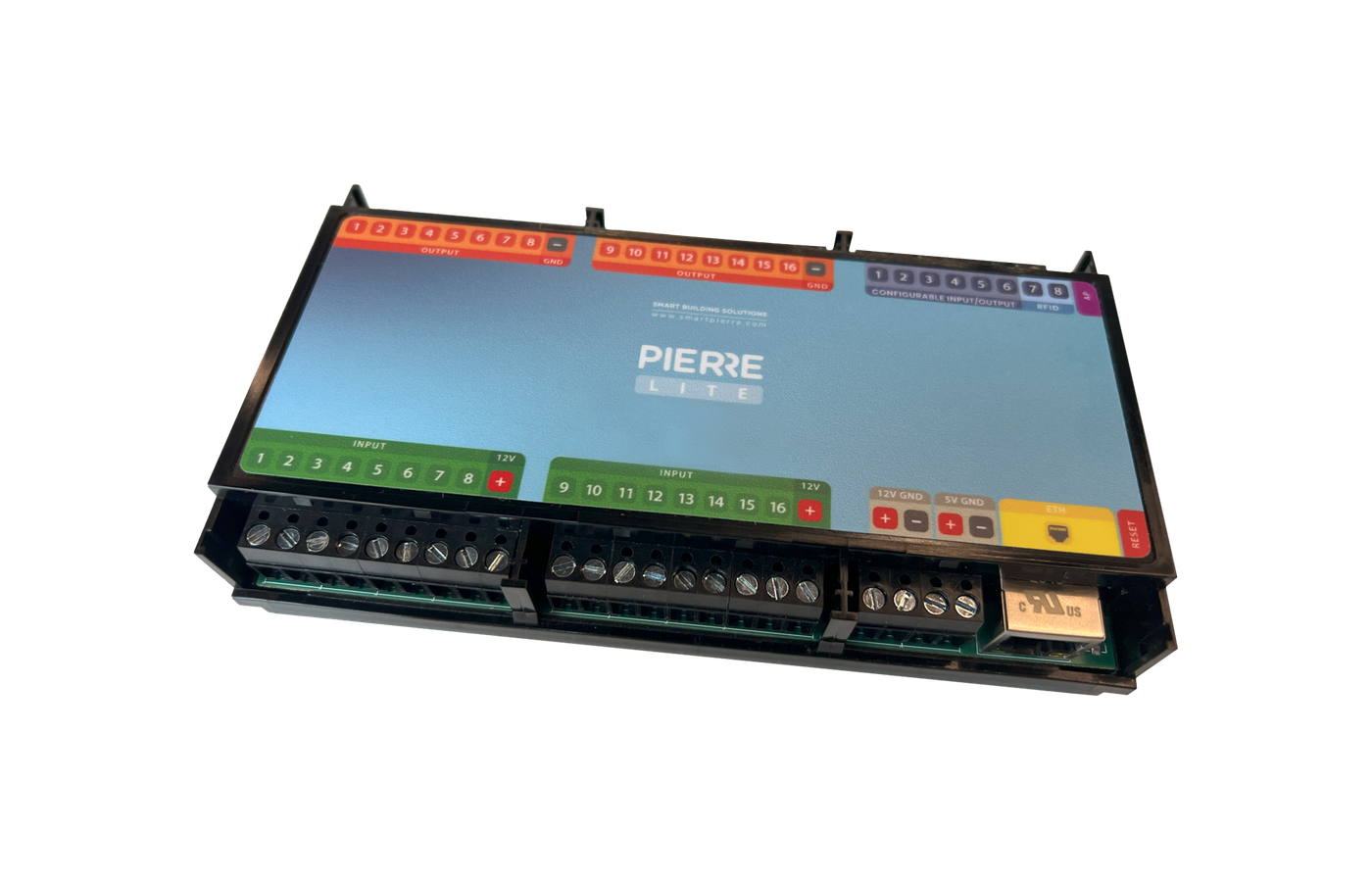
TX – select the appropriate Configurable I/O Pin between 1 and 6 where the TX connection of the Modbus interface is connected.
-
RX – select the appropriate Configurable I/O Pin between 1 and 8 where the RX connection of the Modbus interface is connected.
-
Baud Rate – communication speed used by the connected devices.
-
Parity – parity configuration used by the Modbus network.
-
Stop Bits – number of stop bits used for communication.
The selected communication parameters must match the requirements and configuration of the connected Modbus devices.
Adding Modbus Devices
Once the Modbus RTU interface has been created, compatible Modbus devices can be added to it.
Each device requires:
-
Name – identifies the device within the PIERRE system.
-
Modbus Address – each device on the same Modbus RTU network must have a unique address.
-
Device Integration / Template – the appropriate predefined PIERRE integration must be selected where available.
If no predefined integration is available, compatibility and the required Modbus register configuration must be verified before the device can be integrated.
Communication Parameters
Devices connected to the same Modbus RTU network must use compatible communication settings.
The main parameters are:
-
Modbus Address / Slave ID – unique address used to identify each device.
-
Baud Rate – communication speed, for example 4800, 9600 or 19200 baud, depending on the connected devices.
-
Parity – communication error-checking configuration, typically None, Even or Odd.
-
Stop Bits – typically 1 or 2, depending on the device configuration.
The required settings are defined by the technical documentation and configuration of the connected devices.
Modbus Register Table
The presence of an RS-485 or Modbus interface alone does not guarantee that a device can be integrated into the PIERRE system.
For third-party Modbus devices, the manufacturer's Modbus Register Table or equivalent technical documentation is required.
The documentation should contain, where applicable:
-
register addresses,
-
read/write permissions,
-
data types,
-
scaling factors,
-
valid value ranges,
-
available commands and statuses,
-
Modbus communication parameters.
The functions available in PIERRE depend on the registers provided by the connected device and on the implemented PIERRE integration.
HVAC Integration
Compatible heating, cooling and ventilation equipment can be integrated into the PIERRE system using Modbus RTU.
Depending on the device, its Modbus Register Table and the implemented PIERRE integration, available functions may include:
-
On/Off control,
-
target temperature,
-
measured temperature,
-
heating/cooling mode,
-
fan speed,
-
operating status,
-
alarm or error information,
-
other device-specific parameters.
The availability of these functions is not universal. The exact functions that can be monitored or controlled must be verified individually for each device and integration.
Information Required for Third-Party HVAC Integration
Before integrating a new HVAC device or system, the following information should be provided:
-
manufacturer,
-
exact model number,
-
technical documentation,
-
confirmation of Modbus RTU support,
-
Modbus Register Table,
-
required communication parameters,
-
information about any manufacturer-specific Modbus interface or gateway required by the HVAC system.
Providing a Modbus connection alone does not guarantee compatibility with PIERRE.
Testing and Commissioning
Before PIERRE Modbus integration begins, the HVAC equipment should already be commissioned and operational according to the manufacturer's requirements.
The recommended integration process is:
-
Verify that the HVAC system operates correctly using its original controls.
-
Verify the Modbus communication parameters and device addresses.
-
Test communication with the Modbus device or manufacturer gateway.
-
Verify the required registers and commands against the manufacturer's Modbus documentation.
-
Connect and configure the device in the PIERRE system.
-
Test the required monitoring and control functions through PIERRE.
Any manufacturer-required thermostat, controller, gateway or other system component must remain installed where required for normal operation of the HVAC system.
Modbus TCP and M-Bus Metering
In the PIERRE system, Modbus TCP is used for reading and integrating data from M-Bus meters.
M-Bus meters are connected to the PIERRE system through an appropriate M-Bus–Modbus converter, which makes the meter data available over Modbus TCP.
Depending on the connected meters and converter configuration, the system can be used to read consumption and measurement data from devices such as:
-
water meters,
-
heat meters,
-
gas meters,
-
electricity meters,
-
other compatible M-Bus metering devices.
The available measurement values depend on the connected meters and the configuration and capabilities of the M-Bus–Modbus converter.
PIERRE Displays and Modbus RTU
The following PIERRE Displays support RS-485 / Modbus RTU communication:
-
PIERRE Rio 4"
-
PIERRE Helsinki 6"
These displays can communicate directly with compatible Modbus RTU devices through their RS-485 interface.
The PIERRE Berlin 10" does not provide an RS-485 interface for direct Modbus RTU device communication.
Control Through PIERRE
Once a compatible Modbus device has been successfully integrated, its available functions can be used through the PIERRE system depending on the specific integration.
This may include control or monitoring through:
-
Smart PIERRE application,
-
compatible PIERRE Displays,
-
PIERRE thermostats or room controls,
-
Scenes,
-
Automations.
The exact available functions always depend on the connected device, its Modbus capabilities and the implemented PIERRE integration.
Technical Notes
-
Each device on the same Modbus RTU network must have a unique Modbus Address.
-
Communication parameters must be compatible across devices sharing the same RTU network.
-
RS-485 communication wiring should be routed separately from mains wiring.
-
Network topology, termination, shielding, cable length and maximum number of devices must follow the applicable PIERRE wiring documentation and the requirements of the connected devices.
-
A Modbus interface does not automatically guarantee compatibility with PIERRE.
-
Third-party integrations should always be verified using the manufacturer's current technical documentation and Modbus Register Table.
- In all cases, the person or company performing the delivery and/or installation must guarantee that the unit is equipped for Modbus communication (either as a standard feature of the machine or via an installed add-on module).
- In all cases, it is the responsibility of the person or company performing the delivery and/or installation to assign addresses to the machines and to perform the necessary settings and configuration on the machine's Modbus interface.
- The person or company responsible for delivery and/or installation must hand over a fully functional system to the Pierre technician, who will then integrate the operational system into the Pierre system.
Schemes - Modbus communication via Modbus gateway
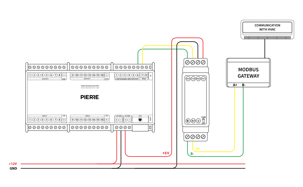
Modbus communication via Modbus gateway
Cables - Modbus communication via modbus gateway
| Position | wires | diameter | type | comment |
|---|---|---|---|---|
| From Pierre to TTL module | 4 | 0.5 mm² | Cat5 UTP | +5V, GND, RX, TX |
| From TTL module to Modbus gateway | 2 | 0.5 mm² | Shielded twisted pair | A+, B- |