PIERRE Partner - Leakage Sensor
Description
The Leakage Sensor is a wired input that detects the presence of water. It is installed where a leak would first appear — under a boiler, behind a washing machine, in a technical room — and its state is available to automation and alarm functions.
Configuration
To add the sensor:
- Open the desired Controller.
- Navigate to Inputs.
- Select Add and choose the sensor type.
- Configure: Name, Dashboards, Role, Picture, Identifier and Signal Type.
- Submit and save the configuration.
To edit a sensor, open the Controller, go to the Inputs tab and select it from the list. The same fields are available, and the sensor can be deleted from here.
Fields
- Identifier — links the input to the electrical project documentation.
- Signal Type — the signal the sensor produces when water is detected.
Advanced Options
The following trigger modes are available in the Advanced section:
| Function | Description |
|---|---|
| Rising | Triggered when the leakage sensor changes from inactive to active state. |
| Falling | Triggered when the leakage sensor changes from active to inactive state. |
| Change | Triggered whenever the leakage sensor state changes. NO sensors. |
| Change Inverted | Triggered whenever the leakage sensor state changes, with inverted output logic. NC sensors. |
Use Change when the input represents a continuous state, such as a flood sensor, smoke detector, gas sensor, or contact sensor.
For sensors with a normally closed (NC) output, use Change inverted. This reverses the input logic so that the I/O becomes active when the input is LOW instead of HIGH.
Important: Change and Change inverted also evaluate the input state when the controller starts. This means that if a sensor is already in an alarm state when the controller powers up, the I/O will immediately become active.
For example, if a flood sensor detects water during a power outage, the sensor can remain in its alarm state. When the controller powers back on, it reads the current input state and will show the flood alarm as active again. This makes Change particularly suitable for safety and alarm sensors.
Use Rising or Falling when you want to react to a change of state (edge) rather than continuously monitor the input state.
Unlike Change, Rising and Falling are edge-triggered. The current input state at controller startup does not itself trigger the I/O. Therefore, they are generally not suitable for alarm sensors where the alarm condition must be detected after a controller restart.
These functions can be used as event triggers for automation rules, notifications, and logic functions.
The default settings for most common cases: Change, Timeout set to 00s.
Automation Applications
- Closing a motorised main valve when a leak is detected.
- Sending a notification to the users assigned to the role.
- Triggering an alarm or siren.
- Switching off equipment in the affected room.
Technical Notes
- Occupies one controller input.
- Detects presence of water at the sensor position only — it does not measure volume or flow.
- Closing a main valve automatically requires a motorised valve wired as a separate output.
Add Leakage sensor from Application
You can add Leakage sensor very fast from the Controllers.
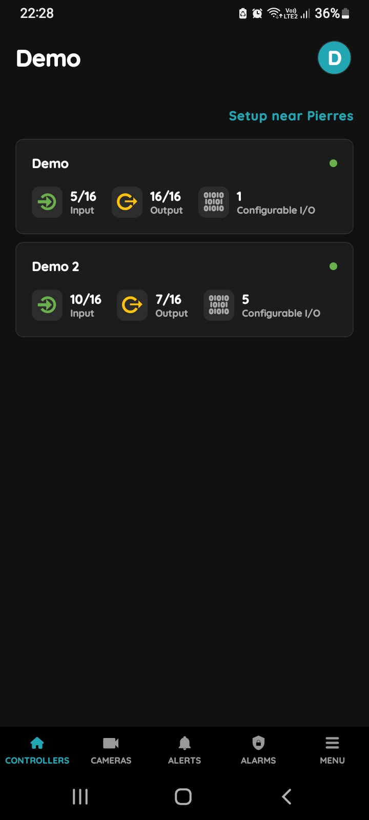
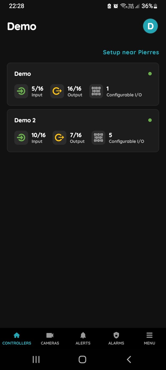
Choose Controller
Tap on the Controller that you would like to add new I/O to.
To edit the I/O, click on the Controller to which the I/O is added.
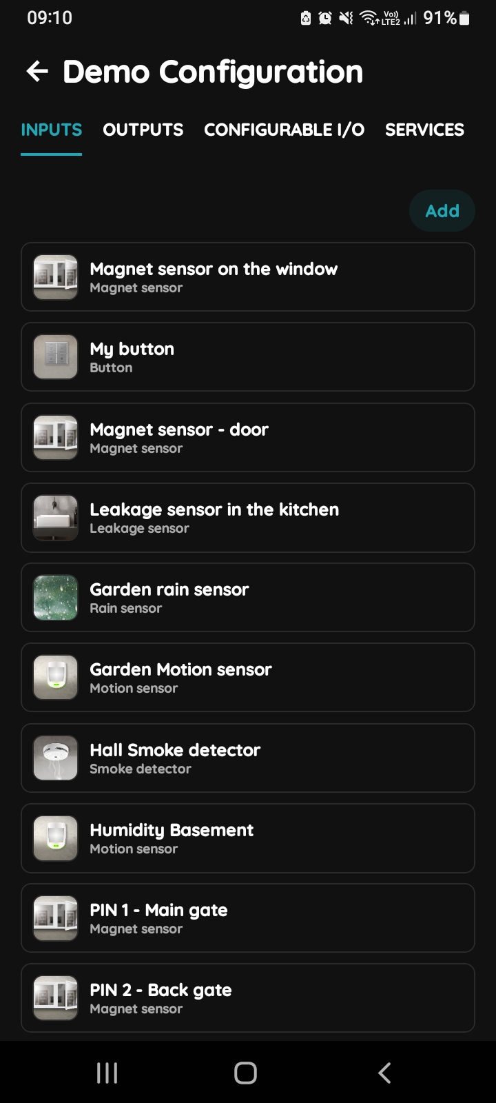
Add button for Inputs
Inputs tab is selected.
List of Inputs is shown.
In order to add new Input tap on the Add button.
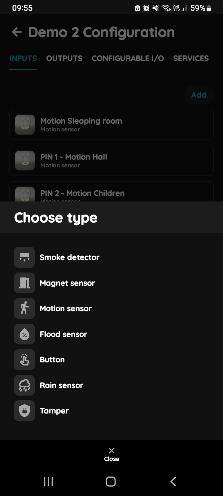
Choose type - Inputs
From the list that is shown tap on the desired I/O that you would like to add.
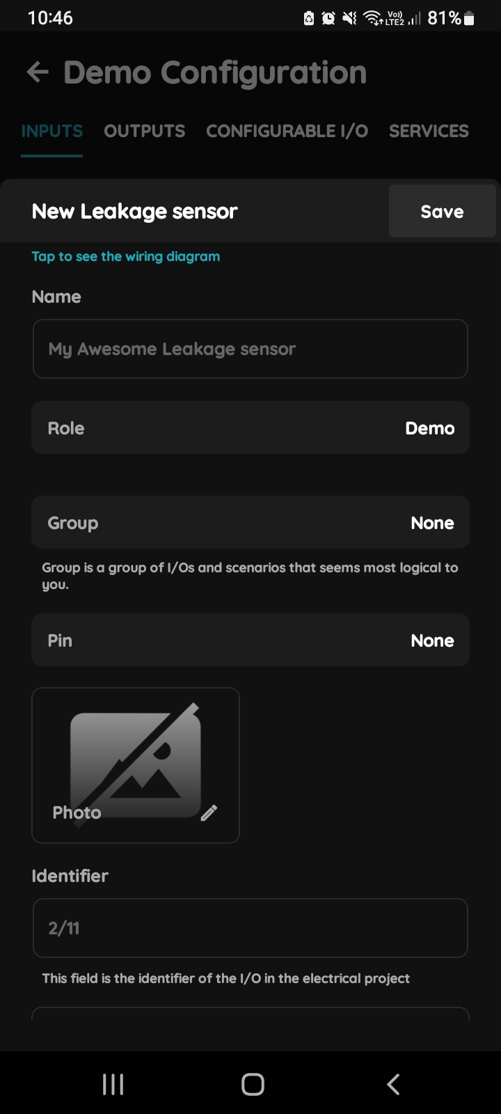
New Leakage sensor
Fill the following form:
- Name - Write the name of the Leakage sensor.
- Role - Choose Role from the list.
- Dashboards - Choose Dashboards from the list. Dashboards are group of I/O and scenarios that seems most logical to you.
- Pin - Choose Pin from the list. Pin is physical place on the Controller where I/O is connected to it.
- Photo - Choose photo for the Leakage sensor.
- Identifier - This field is the identifier of the I/O in the electrical project.
- Advanced - You can choose type of the signal that activates or tiggers the Leakage sensor: rising, falling, change, change inverted.
- Timeout - It is the duration for which the Leakage sensor will remain active in auto mode.
For more details follow next steps.
When you want to confirm your choice tap button Save and Submit.
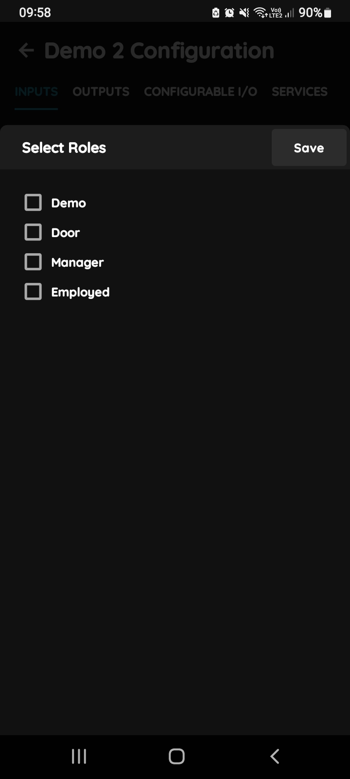
Select Roles - Inputs
Tap in the field Roles.
Select checkbox/checkboxes (for multiple choice) next to the Role/Roles that you would like to choose.
To confirm selection tap the button Save/Done.
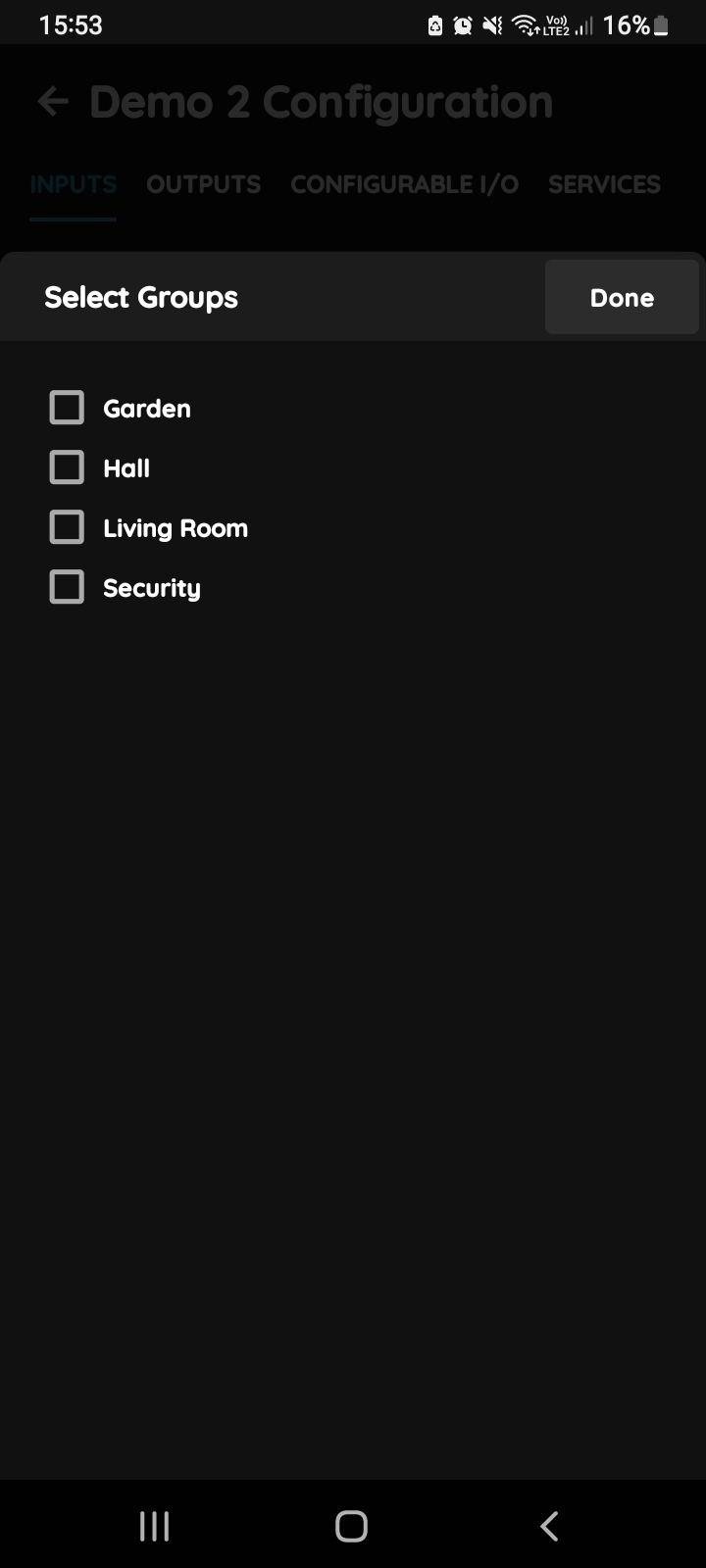
Select Dashboards - Inputs
In this step you should select Dashboards.
Select check box/check boxes next to the desired Dashboards from the list.
When you want to confirm your choice tap button Done/Save.
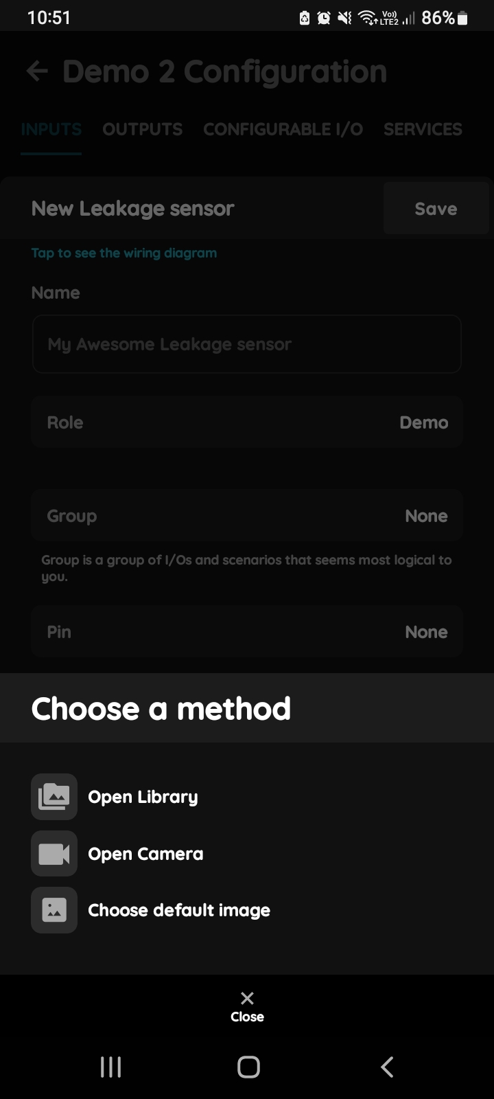
Change photo
Tap on the photo of the Leakage sensor.
You have three options:
Open Library - The phone’s Library will open.
Open Camera - You can take a picture using your smartphone.
Choose default image - These images are prepared in advance in order to provide a complete and seamless experience.
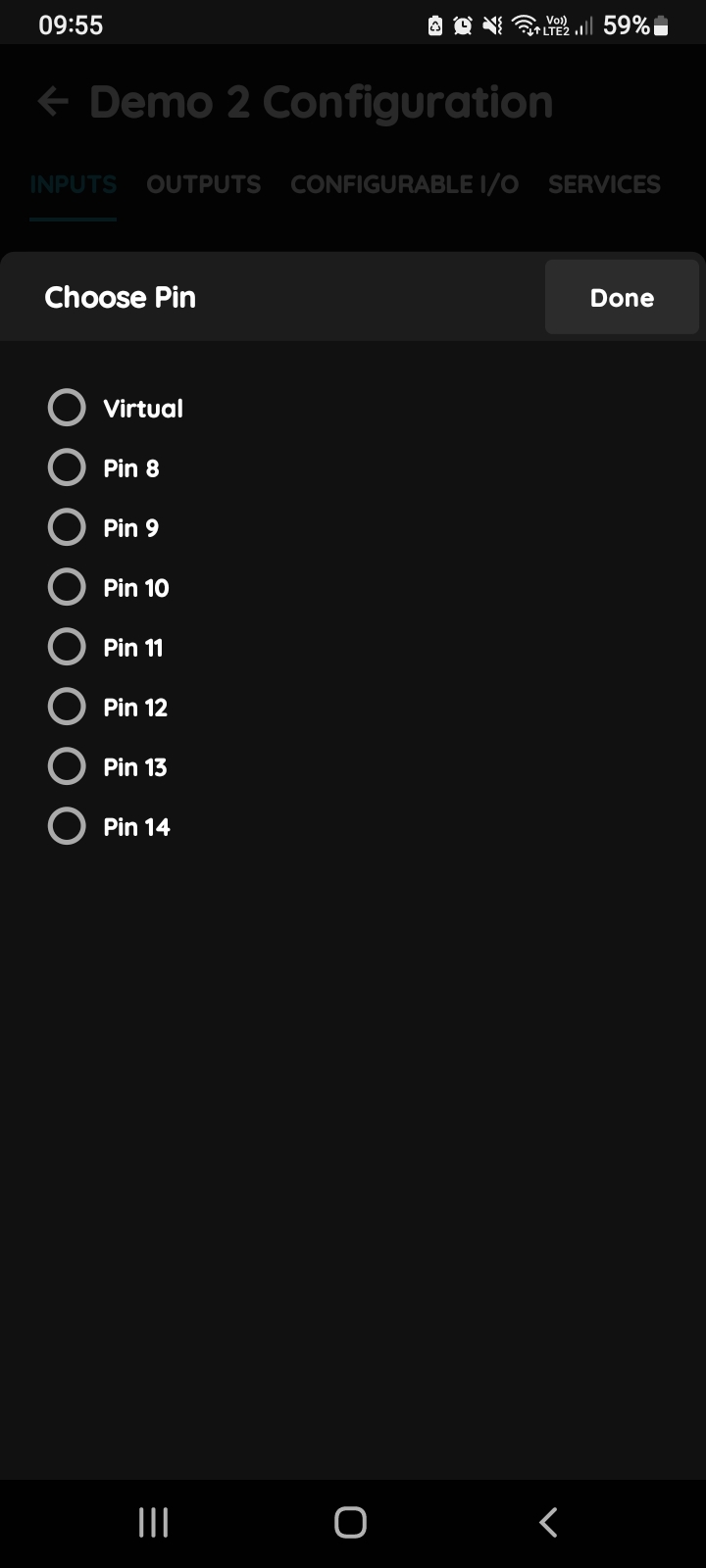
Choose PIn
Tap on the radio button next to the Pin that you would like to choose.
To confirm selection tap on Save/Done.
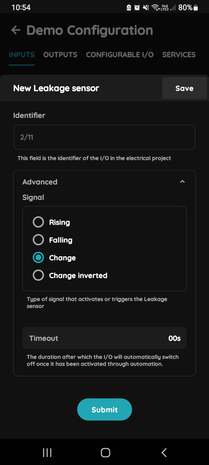
Advanced - New Leakage sensor
Click radio button next to the type of signal that you would like to choose.
You can choose:
- Rising
- Falling
- Change
- Change inverted
You can choose type of the signal that activates or triggers the Leakage sensor.