PIERRE Partner - Push Button
Description
The Push Button input allows connection of external dry-contact push buttons to a PIERRE controller. Each configured button can trigger one or more actions based on the selected interaction type.
Configuration
To create a new Push Button:
- Open the desired Controller in the PIERRE Partner application.
- Navigate to Inputs.
- Select Add Input and choose Push Button.
- Configure the required parameters:
- Name
- Role
- PIN
- Assigned actions
- Save the configuration.
Supported Actions
A Push Button can execute different functions depending on the user interaction:
| Action Type | Description |
|---|---|
| Single Press | Executes the assigned action when the button is pressed once. |
| Double Press | Executes a secondary action when the button is pressed twice. |
| Long Press | Executes an action when the button remains pressed. |
Each action can be assigned independently.
Available Functions
A Push Button can be used to control any supported system function, including:
- Lighting control
- Blind and shutter control
- Door unlocking
- Gate operation
- HVAC control
- Scene activation
- Security functions
- Virtual inputs and outputs
- Automation triggers
Toggle Operation
The Toggle function changes the state of the assigned output with each button press.
Example:
| Current State | Button Press | New State |
| OFF | Press | ON |
| ON | Press | OFF |
This function is commonly used for lighting, relays, and other binary outputs.
Automation Integration
Push Buttons can be used as triggers for automation logic.
Examples:
- Activate a predefined scene.
- Turn off all lighting circuits.
- Close all shutters.
- Enable or disable security functions.
- Execute multiple actions simultaneously.
Editing a Push Button
To modify an existing Push Button:
- Open the corresponding Controller.
- Navigate to Inputs.
- Select the desired Push Button.
- Modify the required parameters.
- Save the changes.
The Push Button can also be removed from the system if it is no longer required.
Technical Notes
- Supports standard dry-contact momentary push buttons.
- Multiple actions can be assigned using Single Press, Double Press, and Long Press events.
- Functions are executed locally by the controller without requiring cloud connectivity.
- Available functions depend on the controller model and system configuration.
- In case of lighting or shutter control, the push button input and the lighting or shutter outputs must be on the same controller!
Add Button from Controllers
Adding Button is fast and easy from the Controllers.
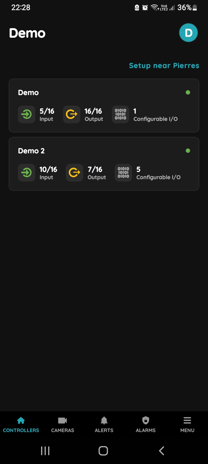
Choose Controller
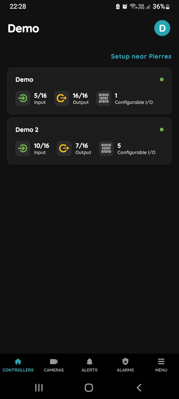
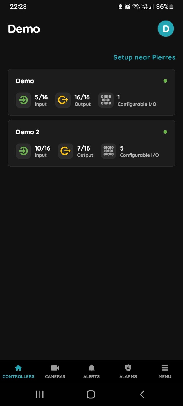
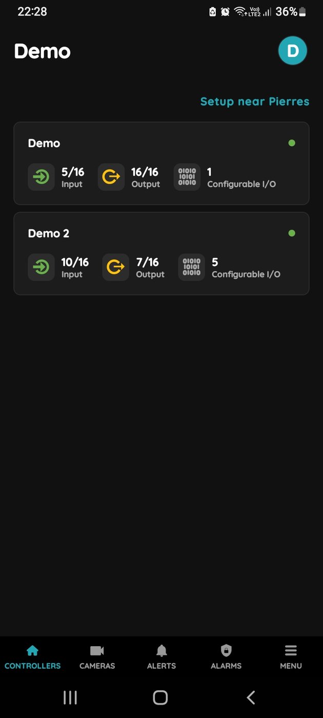
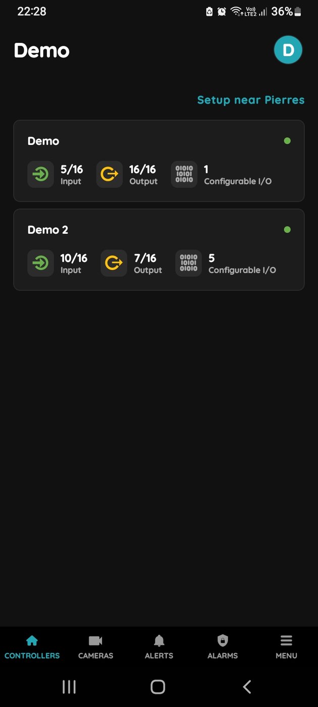
Tap on the Controller that you would like to add new I/O to.
To edit the I/O, click on the Controller to which the I/O is added.
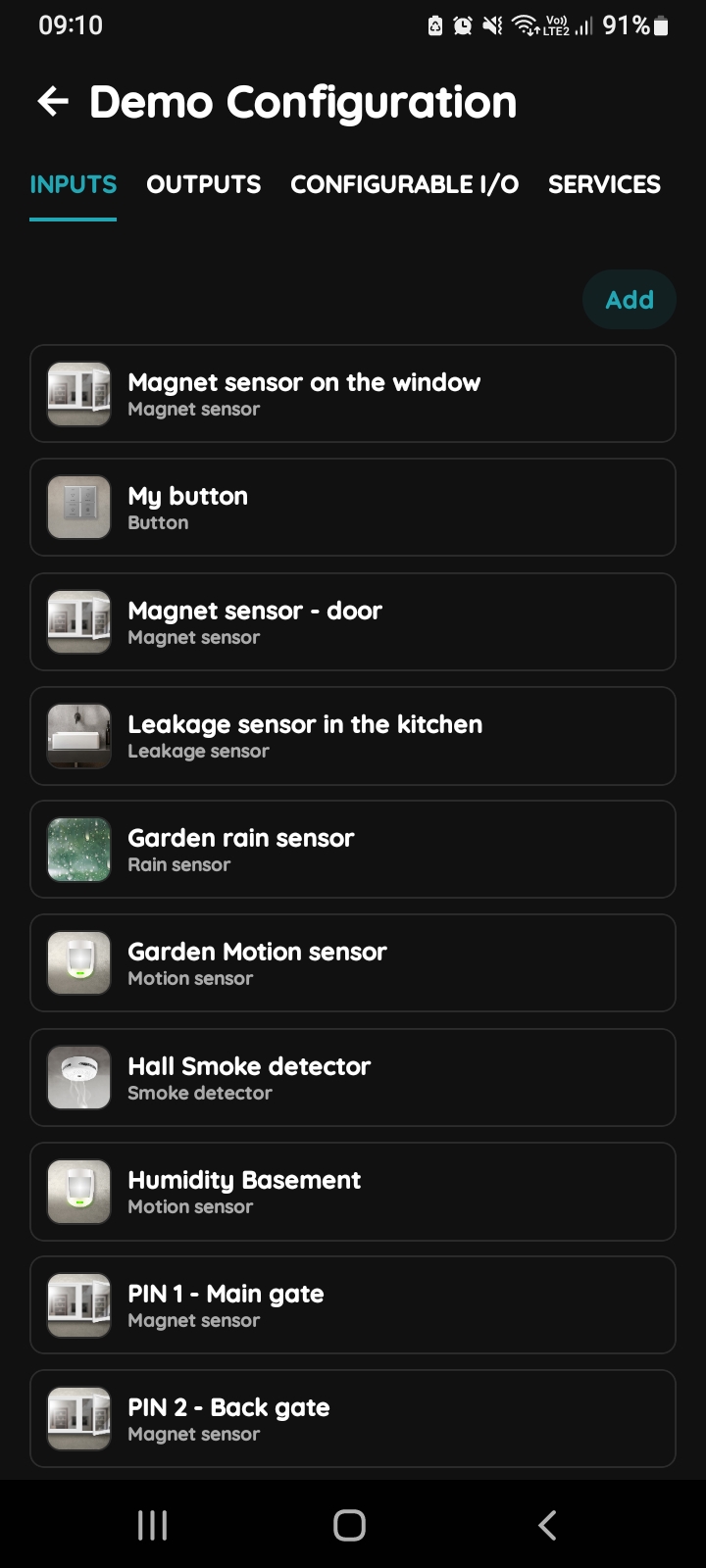
Add button for Inputs
Inputs tab is selected.
List of Inputs is shown.
In order to add new Input tap on the Add button.
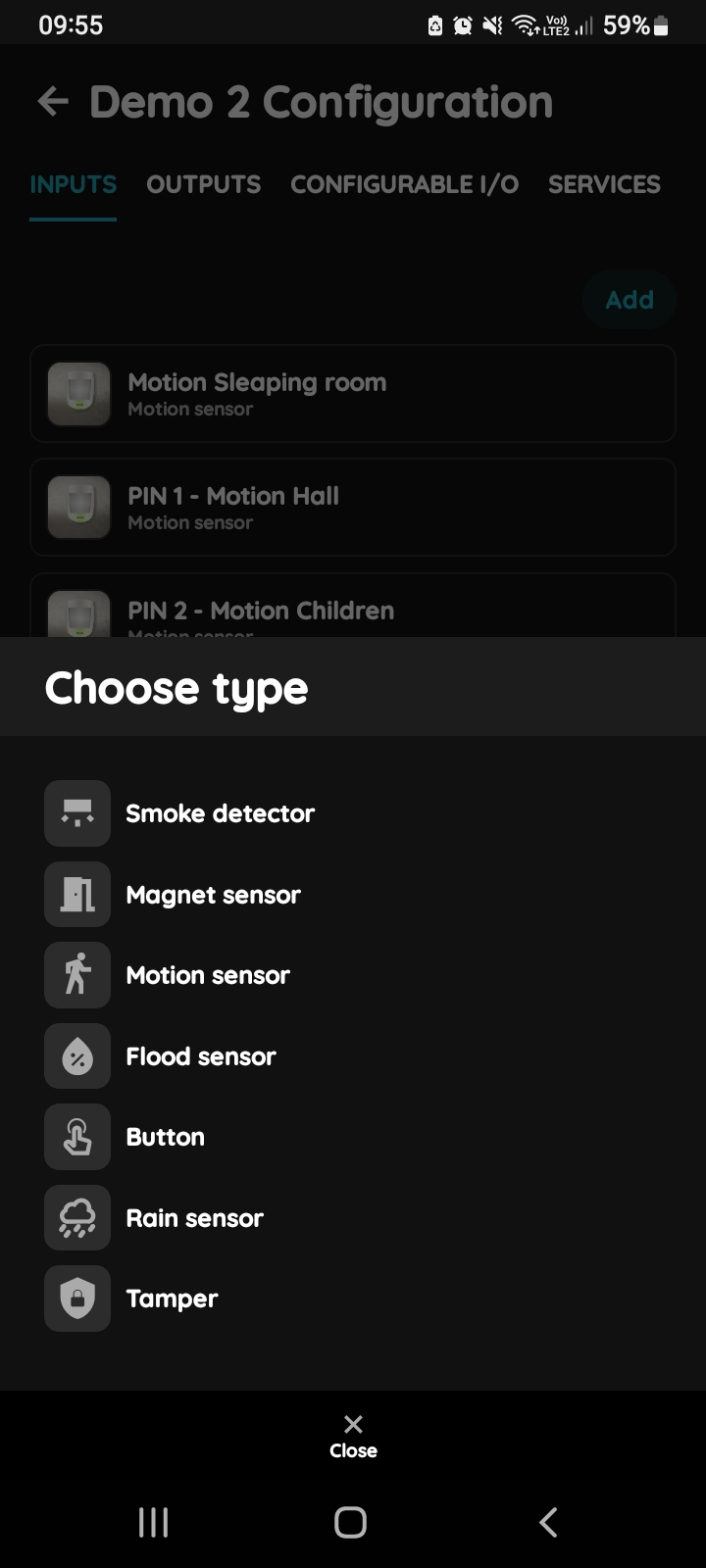
Choose type - Inputs
From the list that is shown tap on the desired I/O that you would like to add.
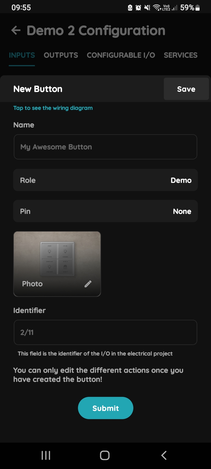
New Button
Fill the following form:
Name - Write the name of the Button.
Role - Choose the Role from the list.
Pin - Choose Pin from the list. Pin is physical place on the Controller where I/O is connected to it.
Photo - Choose photo for the Button.
Identifier -This field is the identifier of the I/O in the electrical project.
For more details about this fields follow next steps.
To confirm your choice tap on Save and Submit.
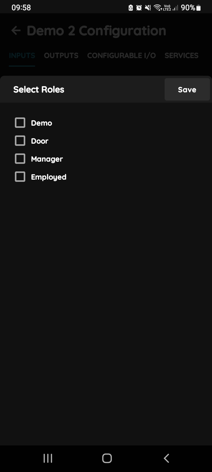
Select Roles - Inputs
Tap in the field Roles.
Select checkbox/checkboxes (for multiple choice) next to the Role/Roles that you would like to choose.
To confirm selection tap the button Save/Done.
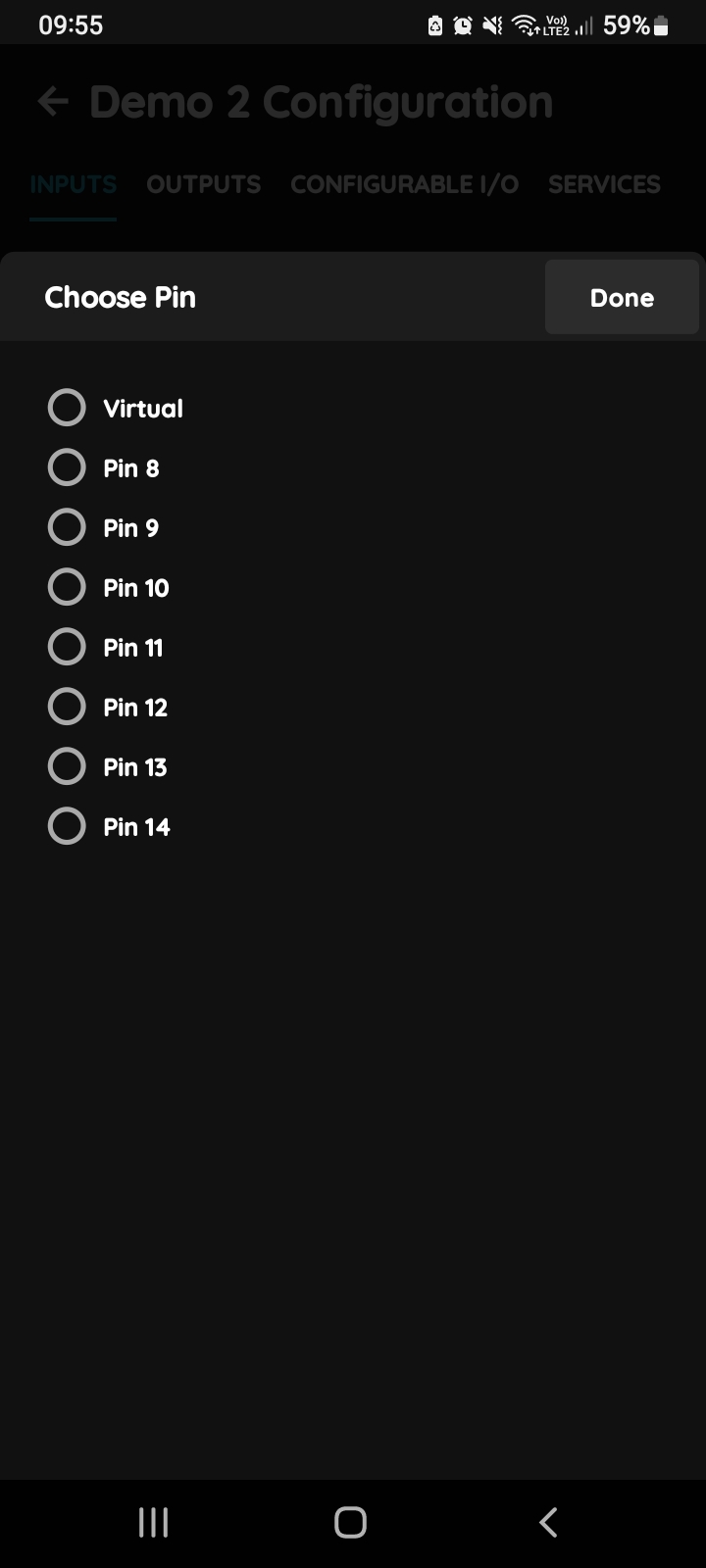
Choose PIN
Tap on the radio button next to the Pin that you would like to choose.
To confirm selection tap on Save/Done.
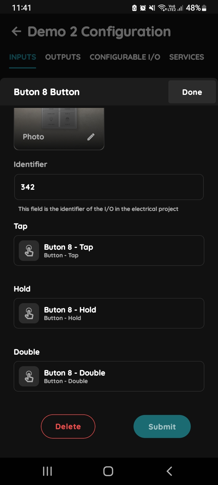
Tap, Hold, Double
Button can be activated if you Tap on it, if Hold it or if it is Double pressed.
Tap on:
- My Button - Tap,
- My Button - Hold,
- My Button - Double, and follow next step that will include more settings.
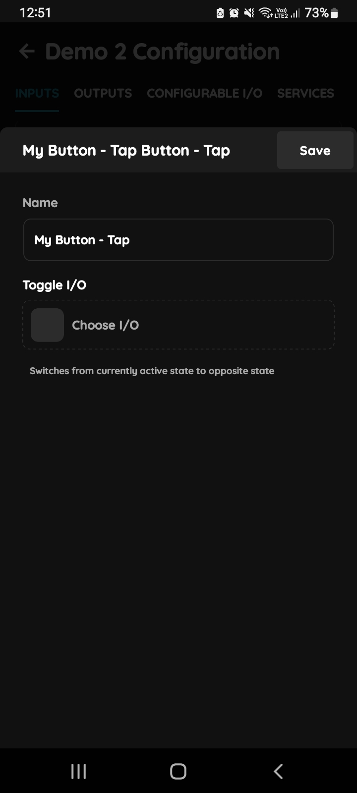
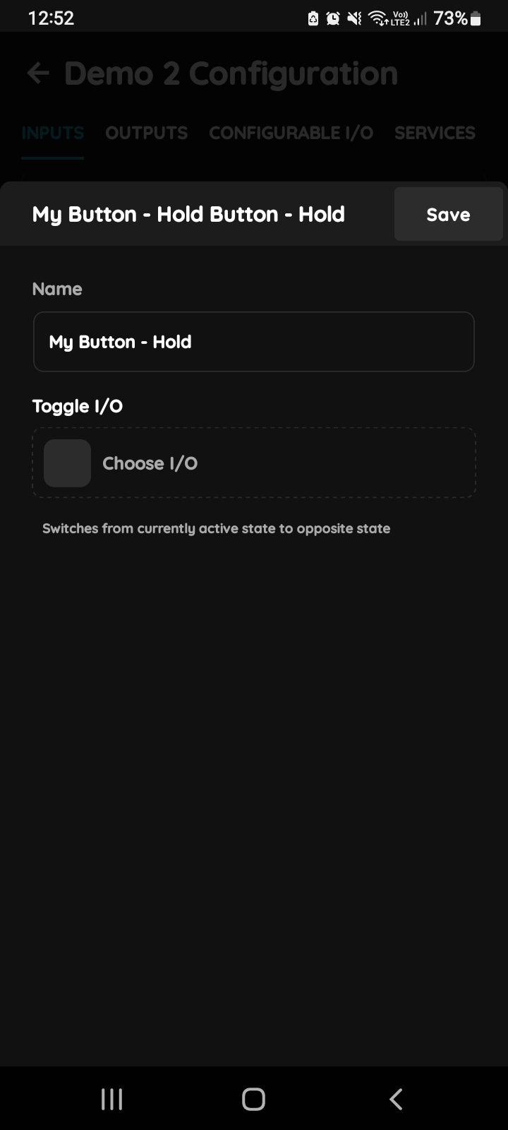
My Button - Tap
You can edit:
- Name - Edit name of the Button.
- Tap in the field Toggle I/O. Toggle - Switches from currently active to opposite state.
To confirm your choice tap the button Done.
Follow next steps for more details.
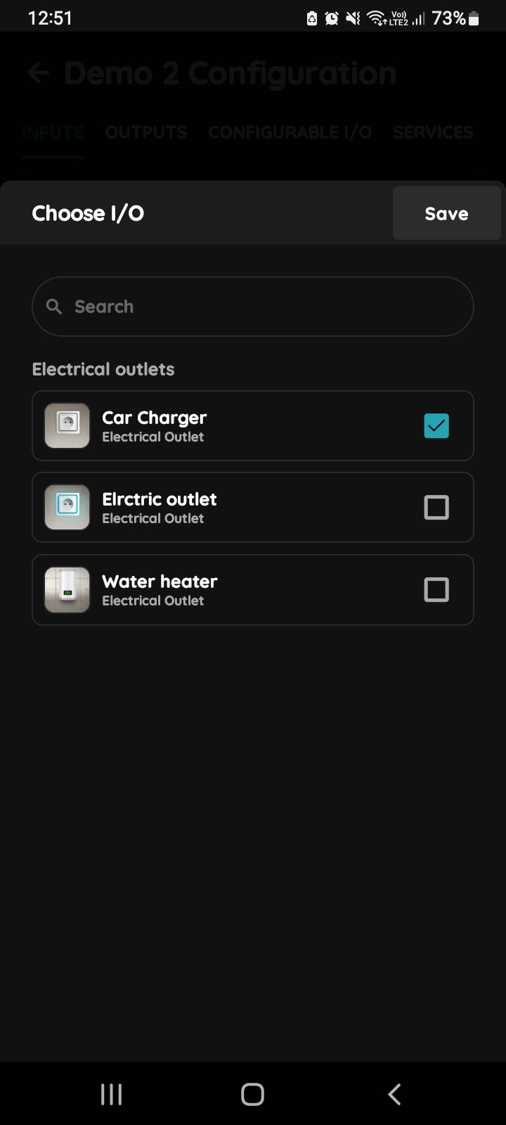
Choose I/O for the My Button - Tap
In this case checkbox next to the Car charger is selected.
Tap on button Save.
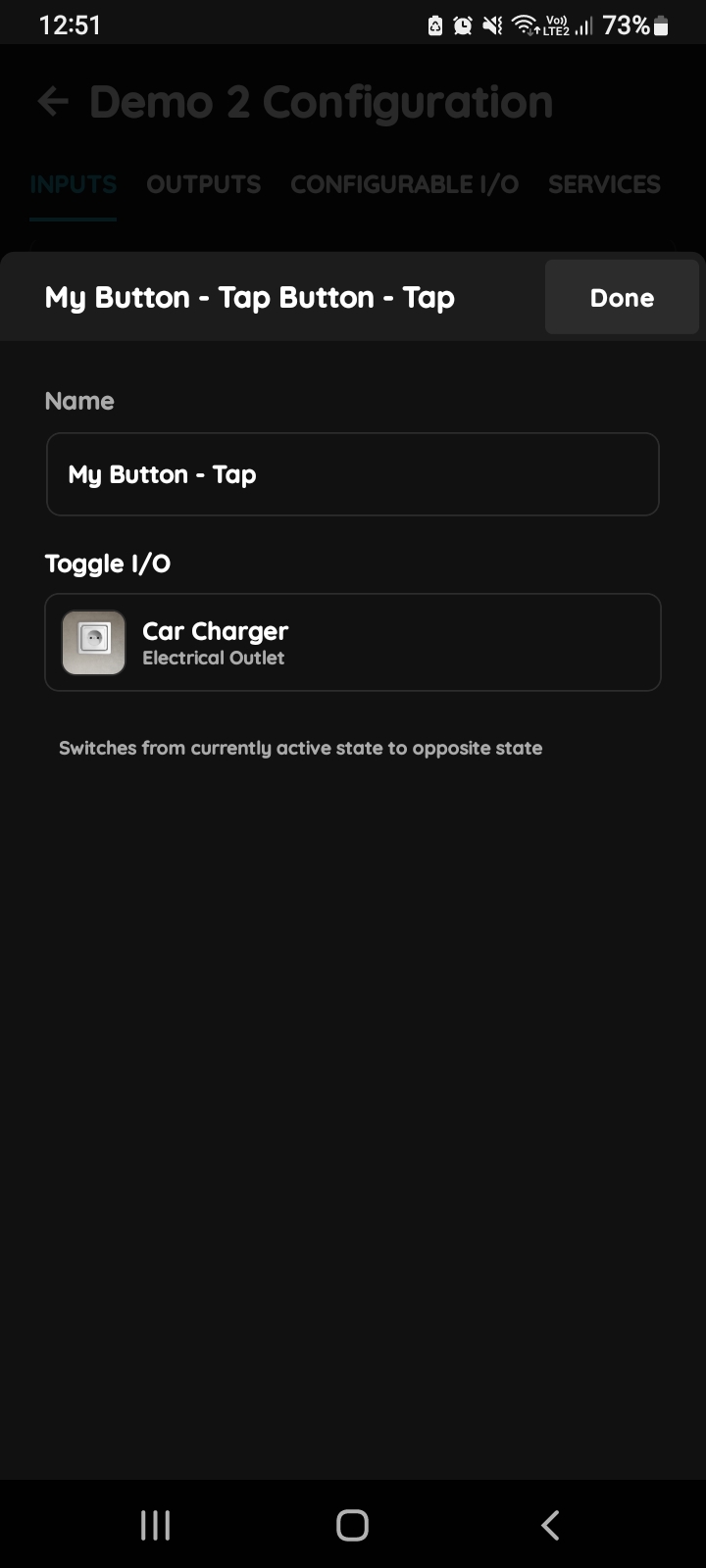
My Button - Tap Button - Tap
It is shown that when you Tap on My Button state of the Car Charger will be changed from active to opposite state and vice versa.
My Button - Hold
You can edit:
- Name - Edit name of the Button.
- Tap in the field Toggle I/O. Toggle-Switches from currently active to opposite state.
To confirm your choice click on the button Done.
Follow next steps for more details.
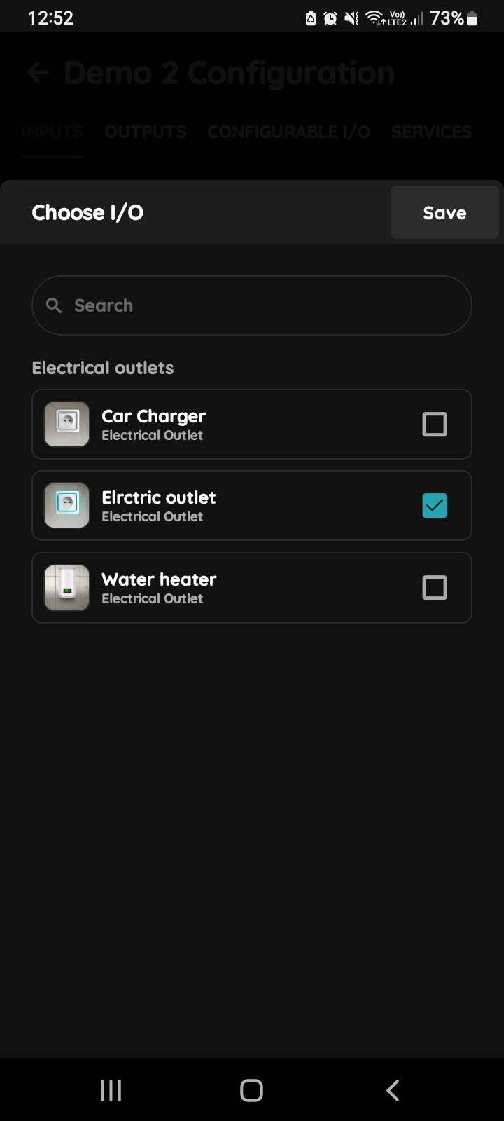
Choose I/O for the My Button- Hold
In this case checkbox next to the Electrical Outlet is selected.
Tap on button Save.
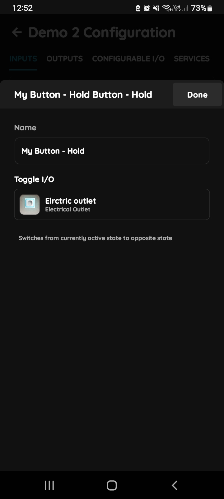
My Button - Hold Button - Hold
It is shown that when you Hold pressed My Button, state of the Electrical Outlet will be changed from active to opposite state and vice versa.
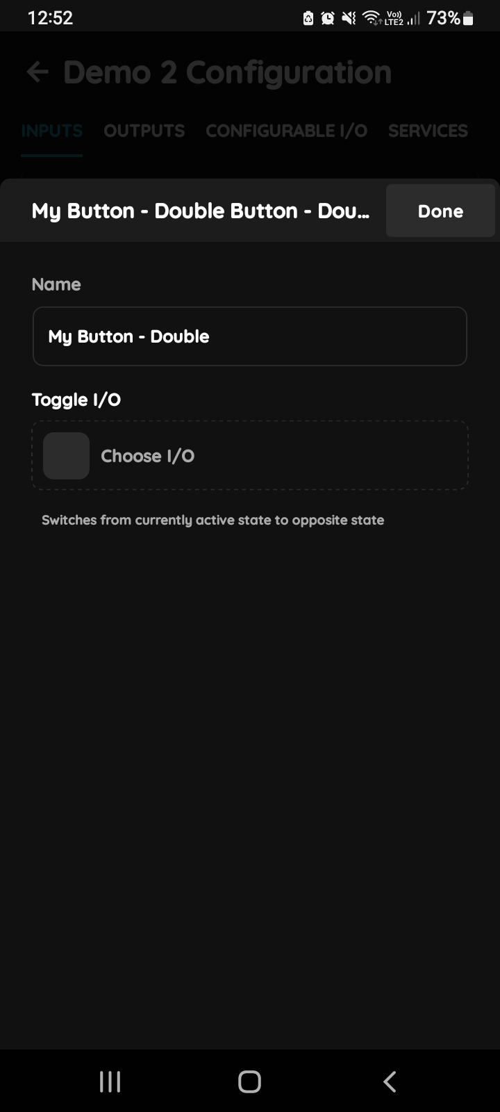
My Button - Double Button - Double
You can edit:
- Name: Edit name of the Button.
- Tap in the field Toggle I/O. (Toggle-Switches from currently active to opposite state).
To confirm your choice tap on the button Done.
Follow next steps for more details.
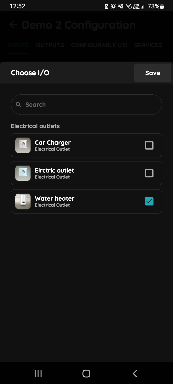
Choose I/O for My Button - Double
In this case checkbox next to the Water Heater is selected.
Tap on button Save.
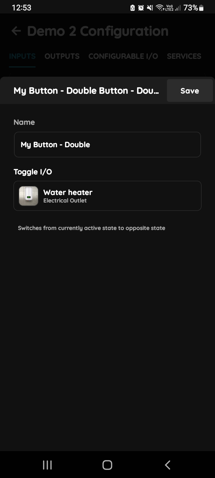
My Button - Double - Double
It is shown that when you Double press My Button, state of the Water Heater will be changed from active to opposite state and vice versa.
Conclusion:
- In this example, one button - My Button manages three I/Os: Car Charger, Electrical Outlet and Water Heater.
- It changes state of the Car Charger when you Tap on it.
- When you Hold it, it changes states of the Electrical Outlet.
- When you double press it, it changes states of the Water Heater.
- In all of these cases it changes states from the active to the opposite state and vice versa when it is pressed according how it is programmed for each I/O.
Schemes
Troubleshooting
Green – Online: the controller is connected to the network and operating normally. Red – Offline: the controller is disconnected from the network, or there is no internet access. White – Commissioning: the controller has started in commissioning mode and is waiting to be commissioned. Light blue – AP mode: the controller is broadcasting its own network for setup or configuration. Dark blue – Selected in the app: the controller is currently selected in the PIERRE Partner app, which helps you identify the physical controller in the cabinet. Purple – Searching for IP address: the controller is waiting to receive an IP address from the router. Orange – Firmware update: a firmware update is in progress; do not power off the controller while the LED is orange.
If not, add it in the PIERRE Partner app. Also check that the push button is assigned to the output it should control (lamp, gate, …).
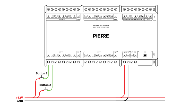
If not, wire it as shown in the diagram. To rule out the device and its cable, briefly bridge the controller's 12 V output to the input the device is wired to. If the input turns green in the app (or the connected output switches), the controller and the input are fine and the fault is in the device or its cable.
If not: The issue is likely related to the connected device itself. Verify that the lamp, door actuator, or other connected equipment is powered and operating correctly. Check for loose connections, damaged wiring, or device-specific faults.
The PIERRE system uses star wiring: every device to be controlled must be wired back to a central point — the distribution box of the PIERRE Controllers. This box can be separate from the high-voltage wiring or combined with it. In larger installations a separate star point per floor is common, with each floor having its own PIERRE distribution box. All of these boxes are connected to the network, which keeps the whole system integrated.