Solution - Contactors
Description
Contactor Control
Description
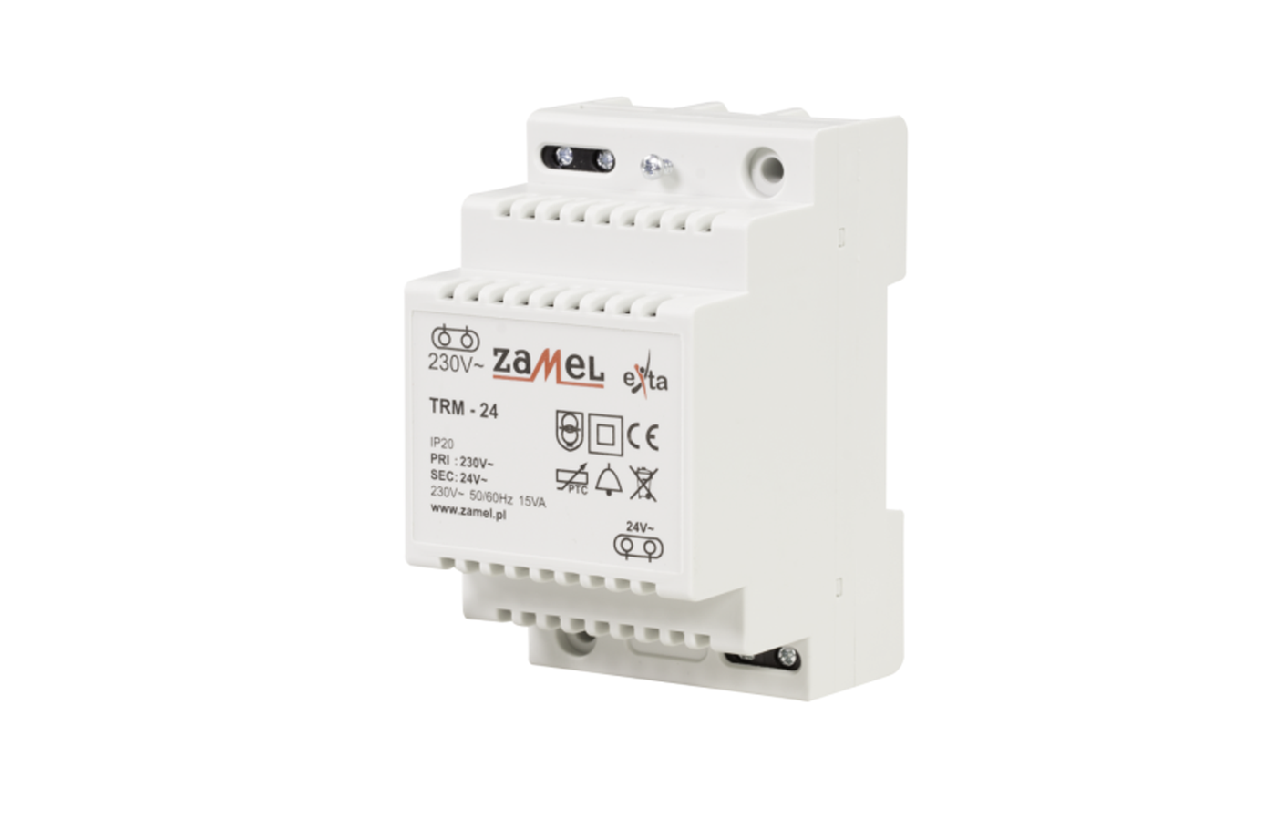
The PIERRE system can control contactors through a Solid State Relay (SSR) or a suitable mechanical relay.
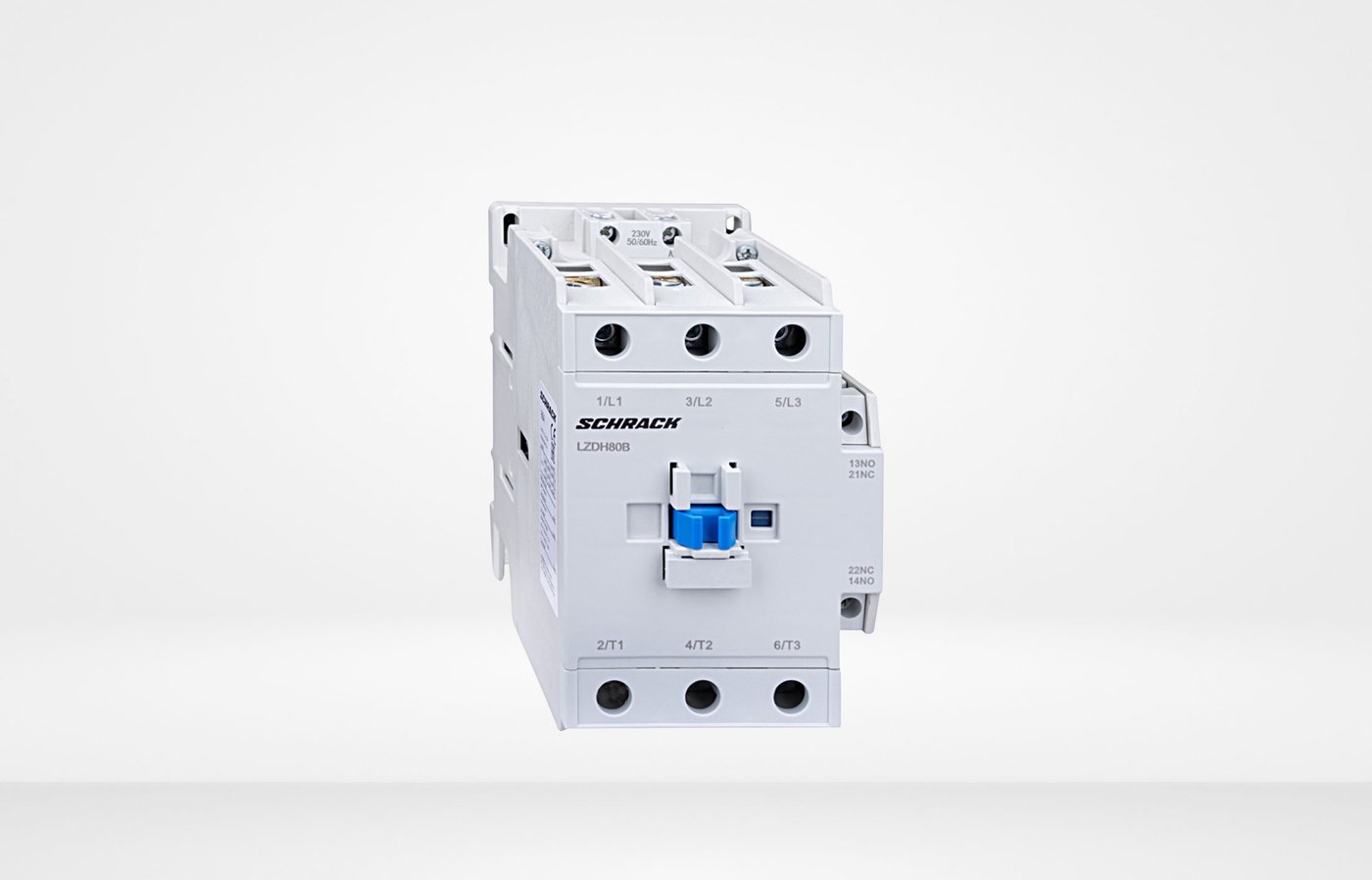
The PIERRE Controller provides a 12 V DC control signal to the relay. The relay switches the voltage required by the contactor coil – for example, 230 V AC – while the contactor switches the connected high-power electrical load.
This configuration allows the low-voltage PIERRE control circuit to control higher-power electrical consumers that cannot be switched directly from the PIERRE Controller output.
Operating Principle
-
The PIERRE Controller activates the appropriate 12 V DC output.
-
The SSR or mechanical relay receives the control signal.
-
The relay switches the supply voltage of the contactor coil.
-
The contactor energizes and switches the connected power circuit.
-
When the control signal is removed, the relay switches off the contactor coil and the contactor returns to its normal state.
Typical Applications
Contactor control can be used for:
-
electric floor heating circuits,
-
HVAC equipment,
-
pumps and circulation pumps,
-
electric water heaters and boilers,
-
sauna heaters,
-
ventilation systems,
-
high-power lighting circuits,
-
other high-power residential, commercial, or industrial electrical loads.
Technical Advantages
-
Higher-power electrical loads are not switched directly by the PIERRE Controller output.
-
The control and power circuits can be appropriately separated by using a suitable relay and contactor.
-
The contactor can be selected according to the power and load type of the connected equipment.
-
The solution can be easily integrated into electrical distribution cabinets.
-
An SSR or mechanical relay can be used, provided that its electrical characteristics are suitable for the specific control application.
Technical Notes
-
In this configuration, the PIERRE Controller provides only the low-voltage control signal.
-
The contactor coil is switched by a suitable SSR or mechanical relay.
-
The actual high-power electrical load is switched by the main contacts of the contactor.
-
The contactor's coil voltage, rated current, number of poles, and utilization category must be selected according to the controlled equipment and the electrical design.
-
The switching voltage and current rating of the intermediate relay must be suitable for the contactor coil.
-
Where galvanic isolation is required, a relay or SSR must be selected whose manufacturer specifications provide the required isolation.
-
When switching inductive loads or contactor coils, the switching device and any required surge suppression must be selected according to the manufacturer's requirements.
-
Mains-voltage and low-voltage control wiring must be appropriately separated.
-
The contactor, wiring, and required overcurrent, short-circuit, and other protective devices must be sized according to the connected load.
-
Installation must be carried out according to the PIERRE technical documentation, the relay and contactor manufacturer's documentation, the electrical design, and applicable electrical safety requirements.
Schemes - Contactor with Mechanical relay
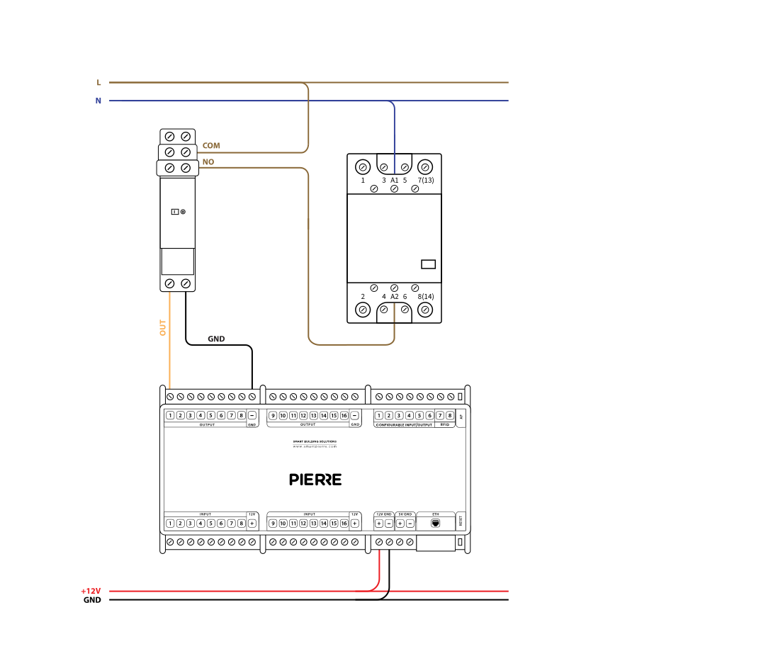
Contactor in PIERRE sistem - Electric schemes
Schemes - Contactor with relay
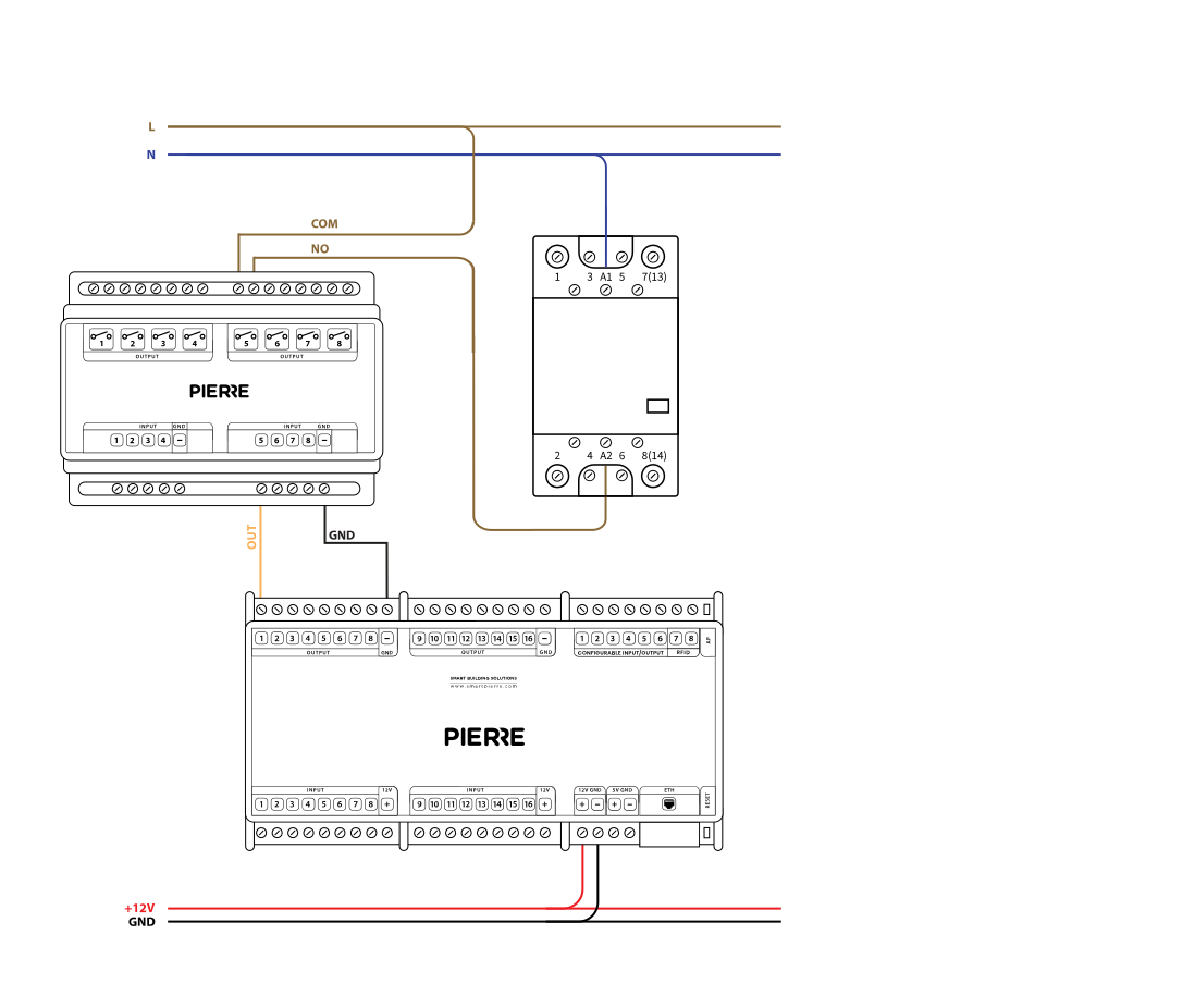
Contactor in PIERRE sistem - Electric schemes
Cables
| Position | Wires | Diameter | Type | Comment |
|---|---|---|---|---|
| From PIERRE to Relay | 2 | 0.75 mm² | H07V-K | OUT, GND |
| From Relay to Contactor | 2 | 1.5 mm² | NYM-O | L, N |
FAQ
Solid-state relays switch silently and have no mechanical wear, so they last longer under frequent switching. They do dissipate heat and need a heatsink at higher currents, and they do not give a galvanic disconnect.
Use good-quality relays with contact protection. If a relay fails, replace that relay; the controller output and the wiring stay as they are. If a spare output is available, the circuit can be moved to it until the relay is replaced.