Solution - Gate, Garage Door, Parking Ramp Control
Description
The PIERRE system controls gates, garage doors, barriers and ramps by emulating the button press their own motor controller expects. This works either through a wired controller input or through a wireless Gate Opener Module.
Typical Applications
- Gates
- Garage doors
- Vehicle barriers
- Parking ramps
- Bollards
- Industrial access systems
Wired Control
A standard dry-contact push button is connected directly to a PIERRE Controller input. Sequence:
- The user presses the push button.
- The Controller receives the input signal.
- An automation rule is executed.
- The configured relay output is activated.
- The controlled device opens, closes or changes state.
Wireless Control
In a wireless installation a PIERRE Gateway and a Gate Opener Module are used, with the push button connected directly to the module. Sequence:
- The user presses the push button.
- The Gate Opener Module detects the input signal.
- The module activates its output.
- The motor controller receives the command.
- The controlled device opens, closes or changes state.
Push Button Requirements
A momentary push button must be used. It generates a short trigger pulse each time it is pressed and does not hold a permanent ON or OFF state, which matches the control inputs found on motor controllers.
Technical Notes
- Standard dry-contact momentary push buttons are supported.
- Wired installations require a PIERRE Controller input; wireless installations require a PIERRE Gateway and a Gate Opener Module.
- A push button provides a pulse and does not indicate the current position of the controlled device. Additional sensors are required to monitor the actual open or closed state.
- The motor controller keeps its own logic, travel limits and safety devices.
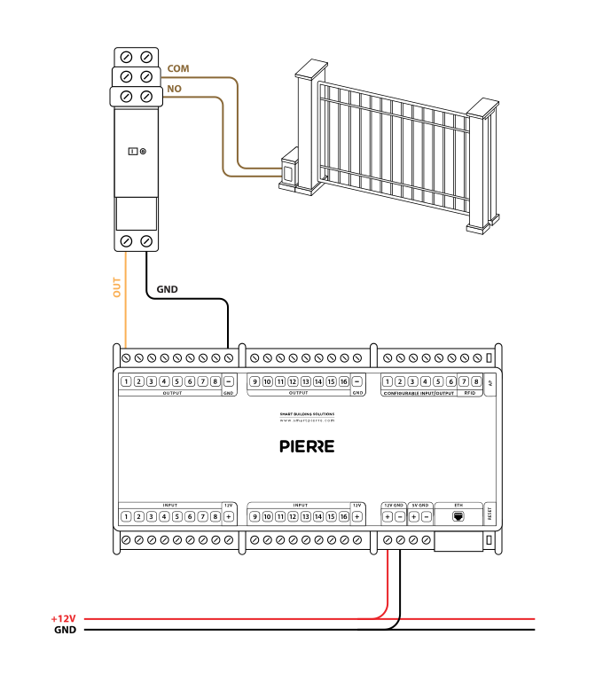
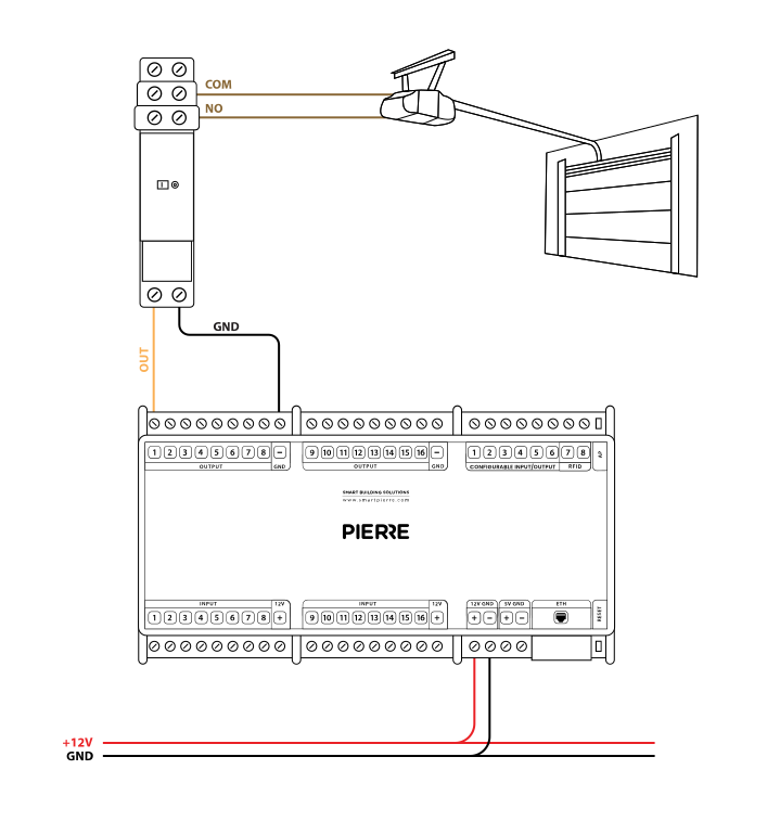
Schemes - Wiring Gate control - dry contact
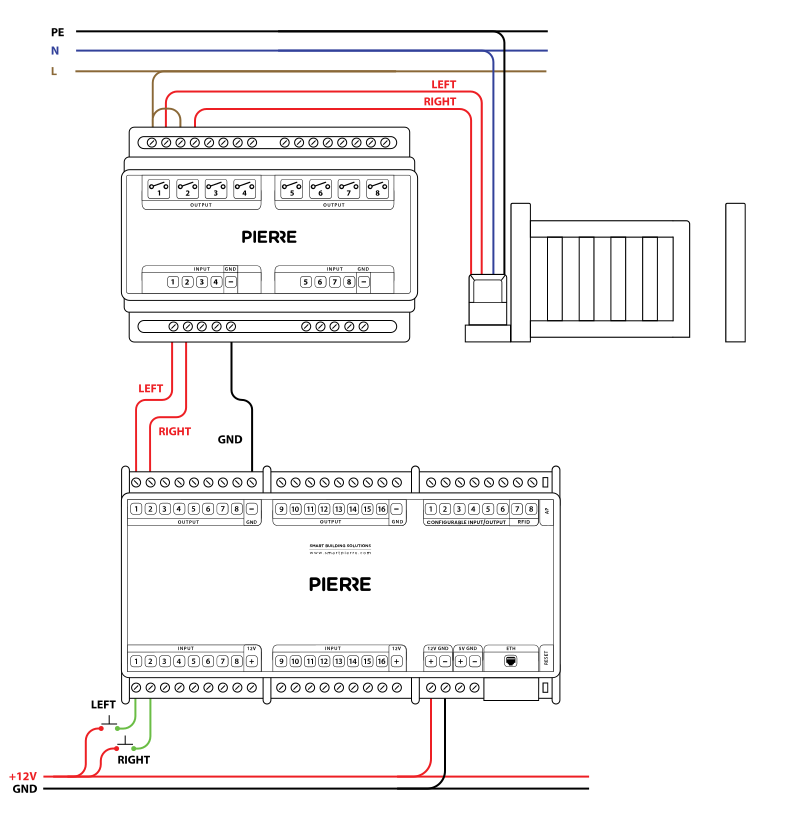
Schemes - Wiring Gate Motors with Separate Open and Close Control Signals
Schemes - Wiring Garage Doors - dry contact
Schemes - PIERRE Controller and push button
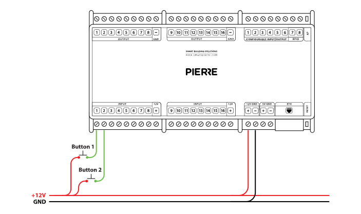
Button - taster wiring - Electric schemes
Schemes - Gate opener module and push button
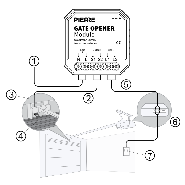
Cables
| Position | Wires | Diameter | Type | Comment |
|---|---|---|---|---|
| From Push button to PIERRE Controller | 2 or 3 | Cat5 | UTP | +12V, SIGNAL (SIGNAL2) |
| From PIERRE Controller to relay | 2 or 3 | 0.75 mm² | H07V-K | GND, OUTPUT (OUTPUT2) |
| From Relay to Gate/Door controller (Dry) | 2 or 3 | Cat5 | UTP | COMMON, SIGNAL (SIGNAL2) |
| From Relay to Gate/Door controller | 4 | 1.5 mm² | NYM-J | L1, L2, N, PE |
Troubleshooting
Green – Online: the controller is connected to the network and operating normally. Red – Offline: the controller is disconnected from the network, or there is no internet access. White – Commissioning: the controller has started in commissioning mode and is waiting to be commissioned. Light blue – AP mode: the controller is broadcasting its own network for setup or configuration. Dark blue – Selected in the app: the controller is currently selected in the PIERRE Partner app, which helps you identify the physical controller in the cabinet. Purple – Searching for IP address: the controller is waiting to receive an IP address from the router. Orange – Firmware update: a firmware update is in progress; do not power off the controller while the LED is orange.
If not, add it in the PIERRE Partner app. Also check that the push button is assigned to the output it should control (lamp, gate, …).
If not, wire it as shown in the diagram. To rule out the device and its cable, briefly bridge the controller's 12 V output to the input the device is wired to. If the input turns green in the app (or the connected output switches), the controller and the input are fine and the fault is in the device or its cable.