Pro
Solution - Pools
2 min read
Intermediate
Updated 2026-11-02
On/Off
Humidity/Temperature/Brightness
Open/close valve
Sauna, Pool
Temperature
Description
Pool equipment is controlled from the PIERRE system through the same outputs and inputs used elsewhere: relays for pumps and valves, dimmable or switched outputs for lighting, and temperature sensors for the water.
What Can Be Controlled
- Water circulation — valves for massage jets, waterfalls and other circuits, each on its own output.
- Water temperature — a temperature sensor in the circulation line provides the reading, and heating or cooling is switched from it.
- Lighting — underwater lighting and the surrounding area, switched or dimmed, and usable in scenarios.
- Covers and valves — motorised covers and actuated valves driven as outputs, manually or on a schedule.
- Pumps and filtration — run on a schedule, or bound to a condition.
Automation
- Filtration on a daily schedule, with the runtime set per season.
- Heating held to a target water temperature, using the measured value from the pool sensor.
- Lighting bound to sunset or to a scenario.
Technical Notes
- Pumps and heaters are switched through contactors sized for their load; the controller relay drives the contactor coil, not the motor.
- Pool areas have their own electrical zone requirements. Follow the local regulation for the installation zone, earthing and equipotential bonding — these are not decided by the control system.
- Use a sensor rated for continuous contact with pool water and mount it in the circulation pipe, not in the basin.
- Keep manual isolation available for every pump and heater, so the equipment can be serviced with the control system running.
Schemes
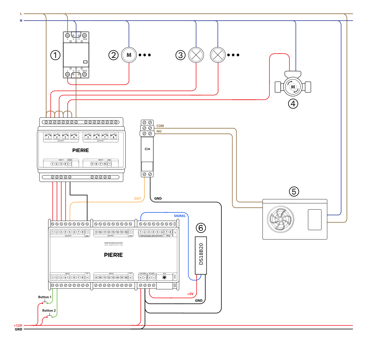
Pool - Wiring | 1. Contactor, 2. Circulation Pump, 3. Light, 4. Valve, 5. Heat Pump, 6. Temperature Sensor - Electric schemes
Cables
| Position | Wires | Diameter | Type | Comment |
|---|---|---|---|---|
| From Button to PIERRE | 3 | 0.5 mm² | Cat5 UTP | +12V, IN1, IN2... |
| From DS18B20 sensor to PIERRE | 3 | 0.75 mm² | H07V-K | +5V, GND, SIGNAL |
| From PIERRE to Mechanical relay | 2 | 0.75 mm² | H07V-K | OUT, GND |
| From PIERRE Controller to relay | 5 | 0.75 mm² | H07V-K | OUT1-4, GND |
| From relay to Contactor | 2 | 1.5 mm² | NYM-O | L, N |
| From relay to Circulation pump | 2 | 2.5 mm² | NYM-O | L, N |
| From relay to Lights | 2 | 1.5 mm² | NYM-O | L, N |
| From relay to Valve | 2 | 1.5 mm² | NYM-O | L, N |
| From Mechanical relay to Heat pump | 2 | 0.75 mm² | H07V-K | COM, SIGNAL |