Solution - Heating and Cooling with 0-10V
Heating and cooling units that offer only an analogue control input are driven from the PIERRE Pro Controller with a 0–10 V signal. The voltage on the line sets the output level of the device continuously, which suits fan speed and valve position. There is no read-back: the controller sets a value, and the device reports nothing about what it did with it. Units with a Modbus interface are covered in the separate lesson Heating and cooling with Modbus.
What You Can Control
- Fan speed of a fan coil unit with a 0–10 V fan input.
- Position of a modulating valve or actuator with a 0–10 V input.
- Speed of a recuperator or ventilation unit with a 0–10 V input.
- Any other device whose 0–10 V control input draws no more than 1 mA.
One line carries one value. A unit with fan speed and valve on 0–10 V needs two channels.
When to Use 0–10 V
- Direction – write only. The app shows the value the controller set, not the state of the unit.
- Feedback – none. Faults on the unit are not seen by PIERRE.
- Needs from the device – a 0–10 V control input and nothing else. No register map, no addressing.
- Prefer Modbus where the unit offers both. Use 0–10 V for simple fan or valve positioning where no feedback is needed.
Operating the Equipment
- From the Smart PIERRE app: target temperature and fan speed on the unit card.
- From a PIERRE display or wired temperature sensor in the room, which gives the controller the room temperature to regulate against.
- From scenarios, for example a Night scene that sets the fan to the lowest speed.
- From automation: a schedule, or a window contact that stops the fan.
The regulation runs inside the controller, so it keeps working when the internet connection is down. Only the app and cloud-started scenarios need the connection.
What You Need
- PIERRE Pro or Lite Controller with one free configurable I/O per channel.
- PIERRE Pro 0–10 V Extender, one channel per controlled value. The controller itself outputs a PWM signal; the extender converts it to 0–10 V.
- A PIERRE display or a wired temperature sensor in the room for the temperature reading.
- Shielded two-core cable from the extender to the unit.
- From the equipment supplier: confirmation of the 0–10 V input, its current draw, and which voltage corresponds to which speed or position.
Wiring
The diagram below shows the extender between the controller and the unit. The cable table lists every run.
- Controller to extender. Connect a configurable I/O and GND of the controller to the extender input. Keep the run short and inside the distribution board.
- Extender to unit. Connect the extender output and GND to the 0–10 V input and its reference of the unit on shielded cable. Route the cable away from mains wiring and connect the shield to ground at one end only.
- Mains. The unit keeps its own mains supply from the distribution board. The 0–10 V line carries a control signal only and does not power anything.
- Valve. Where the fan coil valve is on/off rather than modulating, it stays on a controller relay output as in the On/Off lessons.
Extender limit. The extender is for units whose control input has a maximum short-circuit current of 1 mA. It carries a low-current control signal and does not power a load. A device that sources more than 1 mA into the 0–10 V line must not be connected directly to the extender.
Planning Notes
- Ask the supplier for the input current of the 0–10 V port before ordering. Inputs above 1 mA need an interface relay or an isolator between the extender and the unit.
- One extender channel per controlled value. Count fan and valve separately.
- Check whether the unit expects 0 V or 10 V for off. Some units run at minimum speed at 0 V and need a separate on/off relay to stop completely.
- Plan the room temperature source at the design stage. Without a display or sensor in the room the controller has nothing to regulate against.
- Because there is no feedback, add a temperature alert in the app if the room must never overheat or freeze.
Configuration
All steps are done in the PIERRE Partner application.
- Open the controller and go to the Configurable I/O tab.
- Tap Add and choose the 0–10 V fan coil type. Fill in Name, Group, Role and Pin. Pin is the configurable I/O wired to the extender channel.
- Assign the room temperature source: a PIERRE display or a wired temperature sensor in the same room.
- If the valve is on a relay, add it as an output and link it to the unit as its valve.
- Save. The unit appears in the Smart PIERRE app as a thermostat card with fan speed.
Testing
- Set the fan speed from the app and measure the extender output with a multimeter. It must move between 0 V and 10 V with the setting.
- Confirm that the fan of the unit follows the setting, from the lowest to the highest speed.
- Raise the setpoint above the room temperature and confirm the fan and valve start; lower it and confirm they stop.
- Disconnect the internet and repeat the setpoint change from the display. Regulation must continue.
Step-by-Step Example: Fan Coil in an Office
An office has one fan coil unit with a 0–10 V fan speed input and an on/off valve, and a PIERRE display on the wall.
- Fit the 0–10 V Extender in the distribution board next to the controller. Connect configurable I/O 1 and GND of the controller to extender channel 1.
- Run a shielded two-core cable from extender channel 1 output and GND to the fan speed input and reference of the fan coil.
- Wire the fan coil valve to a relay on controller output 1. The unit keeps its own mains supply.
- In the Partner app open the controller, Configurable I/O, Add, 0–10 V fan coil. Name it Office Fan Coil, choose the Office group and role, Pin: configurable I/O 1. Set the Office display as the temperature source. Save.
- Outputs, Add, Valve. Name it Office Fan Coil Valve, Pin: output 1. Link it to Office Fan Coil. Save.
- Test: set fan speed low, medium and high from the app and measure the extender output at each step. Raise the setpoint and confirm the valve relay closes.
Schemes
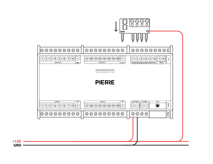
PWM to 0-10V adapter - Needed for 0-10V control - Electric schemes
Cables
| Position | Wires | Diameter | Type | Comment |
|---|---|---|---|---|
| From controller to 0-10 V Extender | 2 | 0.75 mm² | H07V-K | Conf. I/O, GND |
| From 0-10 V Extender to unit | 2 | 0.75 mm² | Shielded twisted pair | 0-10 V, GND |
| From electric box to unit | 2 | 1.5 mm² | NYM-O | L, N |
Troubleshooting
Measure the extender output. If it moves between 0 V and 10 V the wiring to the unit or the unit input setting is wrong; if it does not move, check the configurable I/O pin in the Partner app and the GND connection between controller and extender.
Many units treat 0 V as minimum speed, not off. Add an on/off relay output for the unit and link it, so the controller can stop it completely.
No. 0-10 V is write only. If the unit also has a Modbus port, use the Modbus lesson instead to get state and error codes.
Only if both inputs together draw no more than 1 mA and both units must always run at the same level. Otherwise use one channel per unit.