Solution - Modbus Integration
Overview
Any device with a Modbus interface connects directly to the PIERRE Pro Controller: heating and cooling units, recuperators, sensors, meters and lights. The controller reads and writes the device's registers, so it both commands the device and reads back its real state: on / off, mode, setpoint, fan speed and measured values.
The examples focus on heating and cooling, the most common and most demanding case. The wiring, the register mapping and the configuration are the same for every Modbus device. Units that only accept an analogue signal are covered in the lesson Heating and cooling with 0–10 V.
At a Glance
- Controller: PIERRE Pro.
- Protocols: Modbus RTU over RS485, or Modbus TCP over the local network.
- RS485 capacity: up to 2 lines per controller (one TTL to RS485 converter each), up to 15 devices per line.
- Drivers: ready-made drivers for PIERRE devices and supported brands; Generic Modbus for any device with a documented register table.
- Required from the equipment supplier: the Modbus register table of the exact model. Without it the integration is not possible.
- Offline operation: regulation runs inside the controller and continues without internet.
What You Can Connect
- Fan coil units, heat pumps, air conditioners, recuperators and boilers with a Modbus interface.
- PIERRE Modbus thermostats and the PIERRE Modbus temperature and humidity sensor.
- Third-party Modbus sensors, for example presence and brightness sensors.
- Energy and heat meters over Modbus; M-Bus meters through an M-Bus to Modbus converter.
- Systems on other buses through a Modbus gateway, for example Daikin air conditioners on the DIII bus.
Modbus Compared to 0–10 V and Relay Control
| Modbus | 0–10 V | Relay contact | |
|---|---|---|---|
| Direction | Read and write | Command only | Command only |
| Feedback in the app | Real state of the unit: on / off, mode, setpoint, fan speed | Last command only | Last command only |
| Values per connection | Many: setpoint, mode, fan speed, measurements | One analogue value | On / off |
| Wiring | One bus cable for up to 15 devices | One pair per signal | One pair per contact |
| Needs from the device | Modbus port and register table | 0–10 V input | Potential-free input |
Modbus Basics
Modbus is a master–slave protocol. The PIERRE controller is the master: it asks, the devices answer. A device never sends data on its own. There must be only one master on a line.
Addresses and Line Settings
- Every device on an RS485 line has a unique address (unit ID), 1–247.
- All devices on one line use the same baud rate, parity and stop bits. One device with different settings disturbs the whole line.
Registers
A device exposes its data as numbered registers. The manufacturer's register table lists, for each value, the register type, the address, the data type, the scaling and whether it can be written.
In the PIERRE Partner app every field gets one of four register types: Coil, Holding, Input or Holdings. The type decides which Modbus function code the controller uses to read and write the field, as shown in the table below. Holding and Holdings read the same registers; they differ only in how they write. A field can use a different register for reading and for writing.
Data Types and Scaling
- A register holds 16 bits. Larger values (32-bit integers, floating point) span two consecutive registers. Some devices store the two halves in reverse order; this is corrected with the word swap setting of the device.
- Values are often scaled. A temperature of 21.5 °C is typically sent as 215, so the field is divided by 10.
- Signed values (int16) are used where a value can be negative, for example outdoor temperature.
- Supported data types: uint16, int16, uint32, int32, uint64, int64 and float.
Register Types in the PIERRE Partner App
| Type in the app | Modbus register | Read | Write | When to use |
|---|---|---|---|---|
| Coil | Coil (1 bit) | FC 01 Read Coils | FC 05 Write Single Coil | On / off values the register table lists as coils. |
| Holding | Holding register (16 bit) | FC 03 Read Holding Registers | FC 06 Write Single Register | Setpoint, mode, fan speed: the usual choice for read / write values. |
| Input | Input register (16 bit) | FC 04 Read Input Registers | Cannot be written | Measured values: temperature, humidity, energy. |
| Holdings | Holding register (16 bit) | FC 03 Read Holding Registers | FC 16 Write Multiple Registers | Holding registers on a device that accepts writes only with function 16. Check the function codes in the register table. |
Modbus RTU and Modbus TCP
| Modbus RTU | Modbus TCP | |
|---|---|---|
| Medium | RS485, shielded twisted pair | Ethernet, local network |
| At the controller | TTL to RS485 converter | Network connection, no extra hardware |
| Where to add it in the Partner app | Configurable I/O tab | Services tab |
| Device identification | Address 1–247 on the line | IP address and port (usually 502), plus unit ID |
| Capacity | 2 lines, up to 15 devices per line | Per IP address |
| Line settings | Baud rate, parity and stop bits must match | Not applicable |
How PIERRE Maps a Modbus Device
Every Modbus device is described in PIERRE in four levels:
- Interface – the Modbus RTU line or Modbus TCP connection.
- Device – one unit on that interface, with its address.
- I/O – what the device represents: Fan Coil, Temperature Sensor, Energy, Volume and so on.
- Fields – the values of the I/O, such as Active, Mode, Target or Value. Each field is linked to a register.
With a ready-made driver the fields are already mapped: enter the name and address and the device works. With Generic Modbus you define for every field:
- the register address and data type, including values that span two registers;
- whether the field is read, written or both;
- transformations: divide, multiply, add, subtract, swap (value mapping, e.g. the device's 3 means PIERRE's 2) and mask (selects bits of a register);
- the polling interval and access mode.
Register Addresses
Addresses in PIERRE start at 1. Enter every address exactly as it appears in the manufacturer's register table, without adding or subtracting an offset.
Polling Interval
Every I/O type has its own default polling interval. Keep the default, especially for fan coils. Many units accept a command in one register and report the result in another, with an internal delay. Polling too fast reads the old value before the unit has updated it, so the app shows the setpoint jumping back, and it also loads the bus.
Register Fields
When you add a Generic Modbus device, Select Register Fields offers nine fields. Which of them the controller uses depends on the I/O type. Both are listed in the tables below.
The example after them shows how a register table translates into fields. The addresses are illustrative only; every manufacturer's table is different, so always work from the table of the exact model. Room temperature is not a field of the heating device: read it with a separate Temperature I/O (Value field).
Register Fields in Generic Modbus
| Field | What it carries | Direction | Value |
|---|---|---|---|
| Active | On / off state. Switches lights and alarms; reports the state of door / window, tamper and presence inputs; for heating and cooling devices it reports whether the unit is running. | Read / write for outputs. Read only for inputs and for heating and cooling devices. | 0 / 1 |
| Mode | Operating mode of a heating or cooling device. 0 means off. Map the device's own mode values with swap. | Read / write | Integer |
| Target | Setpoint temperature of a heating or cooling device. | Read / write | Decimal; scale with divide / multiply |
| Intensity | Level: fan speed of a heating or cooling device, fan level of a recuperator, brightness of a dimmable light (0–100 %). For an RGB light, four consecutive registers: red, green, blue, white (0–255 each), written with Holdings. | Read / write | Integer |
| Value | Measured value of a sensor or meter: temperature, humidity, moisture, conductivity, volume, flow, power, energy, voltage, current, brightness. | Read only | Decimal; scale with divide / multiply |
| HeatingSeason | Heating or cooling season of a heating or cooling device. Written when the season changes in PIERRE. | Read / write | Integer; map with swap |
| ModeSeason | One register that holds both on / off and the season: 0 = off, 1 = on in cooling, 2 = on in heating. Use it instead of Mode and HeatingSeason on devices that combine them. | Read / write | Integer; map with swap |
| Minutes | Clock minutes of the device. The controller reads it and writes the current local minute when it differs. | Read, written automatically | 0–59 |
| Hours | Clock hours of the device. Kept in sync the same way as Minutes. | Read, written automatically | 0–23 |
I/O Types and Their Fields
| I/O type | Fields used |
|---|---|
| Heating and cooling device, passive heating | Active, Mode, Target, Intensity, HeatingSeason, ModeSeason, Minutes, Hours |
| Light, alarm | Active |
| Dimmable light, recuperator, DC recuperator | Active, Intensity |
| RGB light | Intensity (four registers: R, G, B, W) |
| Door / window, tamper, presence | Active (read only) |
| Temperature, humidity, moisture, electrical conductivity, volume, flow, power, energy, voltage, current, brightness | Value |
Example: Fan Coil as a Heating and Cooling Device (Illustrative)
| Field | Register type | Address | Data type | Transformation | Access |
|---|---|---|---|---|---|
| Active | Coil | 1 | bit | – | Read |
| Mode | Holding | 2 | uint16 | Swap: device mode values to PIERRE values | Read / write |
| Target – command | Holding | 3 | int16 | Multiply by 10 | Write |
| Target – read back | Input | 11 | int16 | Divide by 10 | Read |
| Intensity (fan speed) | Holding | 4 | uint16 | Swap: device fan levels to PIERRE levels | Read / write |
| HeatingSeason | Holding | 5 | uint16 | Swap: device season values to PIERRE values | Read / write |
Why Every Modbus Integration Is a Project
Modbus standardizes how data travels, not what it means. Every manufacturer decides its own register addresses, scaling and value codes, and the same brand can use a different table on a different gateway model.
Example: Midea Indoor Temperature
The value in register 1606 is not in degrees. To get °C the controller applies a chain of transformations: subtract 30, divide by 2, subtract 5. A raw value of 80 gives (80 − 30) ÷ 2 − 5 = 20 °C. Without the manufacturer's documentation this formula cannot be guessed.
What This Means for Every Project
- Only a working system can be integrated. The equipment must be installed, commissioned and running on its own first.
- Complete documentation from the manufacturer: the register table of the exact model and gateway model, the line settings and the unit numbers.
- Nothing is guaranteed before a test on a real unit. Never promise that a device works out of the box.
- A trained partner on site checks every function after the configuration: on / off, mode, setpoint, fan speed and read-back.
Planning
Before Quoting the Job
- Confirmation from the supplier that the unit supports Modbus, with the exact manufacturer and model.
- The Modbus register table of that model. A unit with a Modbus port but no documented registers cannot be integrated.
- The unit commissioned and working on its own. An integration cannot fix equipment that is not commissioned.
What You Need
- PIERRE Pro Controller.
- Modbus RTU: one TTL to RS485 converter per line and shielded twisted-pair bus cable.
- Modbus TCP: the unit and the controller on the same local network.
Design Rules
- At most 15 devices per RS485 line, at most 2 lines per controller.
- Reserve the controller pins: pin 7 and pin 8 for the converter RX, one pin from 1 to 6 for each converter TX.
- Plan the bus as one line from device to device. Keep a line under 100 m.
- Group devices with the same line settings on the same line.
- Where several apartments share a circulation pump, plan the pump as a controller output with an automation: the pump runs whenever any valve is open.
Wiring
An RTU installation has three parts: the controller to converter connection inside the distribution board, the RS485 bus from the converter to the devices, and the mains supply of the devices. The pin assignment and the bus rules are in the tables below, followed by the wiring diagram and cable list for each device type.
Controller to Converter
One Cat 5e run of four conductors: 5 V and GND from the controller, TX and RX to the controller pins. Keep the run short and inside the distribution board.
On every converter:
- Switch the 120 Ω termination DIP switch ON. The converter is one end of the line.
- Use a converter with built-in pull-up and pull-down resistors.
- Fit two 470 Ω resistors: one between RX and VCC, one between TX and GND.
Device Settings
- PIERRE Modbus thermostats: address, baud rate and parity are set in the thermostat menu.
- PIERRE temperature and humidity sensor: 9600 baud, no parity, 1 stop bit.
- Third-party units: as given in the manufacturer's documentation, matched to the line.
Mains
Bring L and N to each 230 V thermostat or unit from the distribution board on 1.5 mm² NYM-O. Mains never runs in the bus cable.
Converter Pin Assignment
| Converter | TX | RX | Note |
|---|---|---|---|
| Converter 1 | Pin 1 (any pin 1–6) | Pin 7 | Recommended |
| Converter 2 | Pin 2 (any pin 1–6) | Pin 8 | Recommended |
RS485 Bus Rules
| Rule | Requirement | Why |
|---|---|---|
| Topology | One line from device to device. No star, no branches. | Branches cause reflections and unstable readings. |
| Termination | 120 Ω at both ends: the converter DIP switch and the last device. | A missing terminator is the most common cause of errors. |
| Cable | Shielded twisted pair; A+ and B− on the same pair. | The twisted pair cancels interference. |
| Polarity | A+ to A+ and B− to B− on every device. | Swapped wires mean no communication with that device. |
| Shield | Connected to ground at one end only. | Grounding both ends creates a ground loop. |
| Reference ground | A third conductor between converter GND and device GND, where the device has its own supply (thermostats, gateways). Use the second pair of a 2 × 2 cable. | Keeps the devices within the common-mode range of RS485. |
| Addresses | Unique on each line, 1–247. | Two devices with one address answer together. |
| Line settings | Same baud rate, parity and stop bits on every device. | A mismatched device disturbs the whole line. |
| Length | Under 100 m per line. | Keeps the line robust against cable quality and on-site noise. |
Schemes - Thermostat
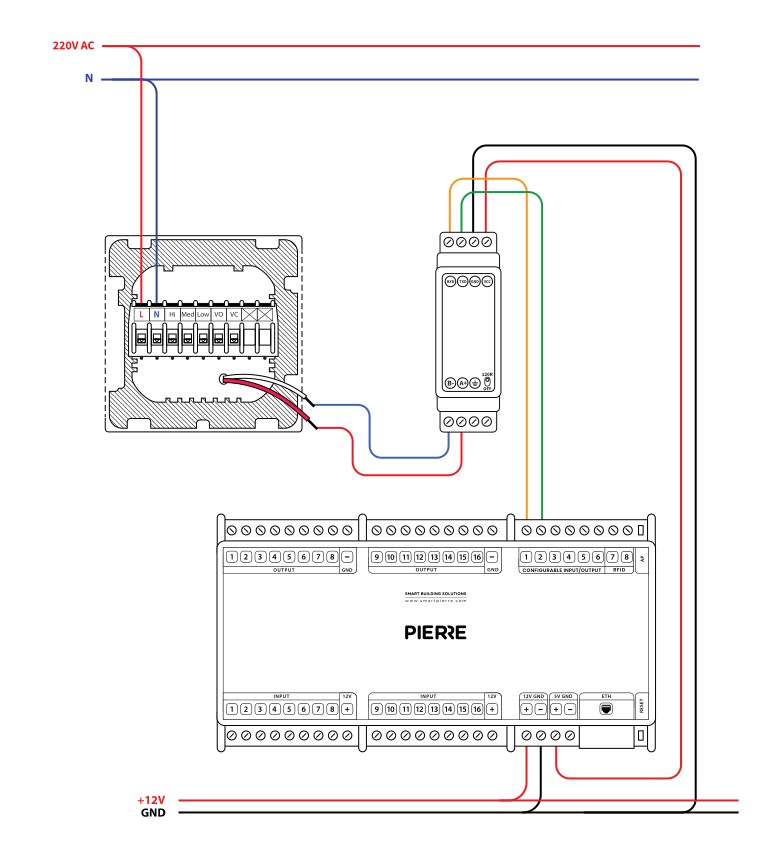
MODBUS Thermostat - Electric schemes
Cables - Thermostat
| Position | Wires | Diameter | Type | Comment |
|---|---|---|---|---|
| From PIERRE controller to TTL module | 4 | 0.25 mm² | Cat 5e U/UTP | +5V, GND, RX, TX |
| From TTL module to thermostat | 3 | 0.5 mm² | Shielded twisted pair, 2 × 2 | A+, B− on one pair; GND reference on the second pair |
Schemes - Temperature & Humidity modbus sensor
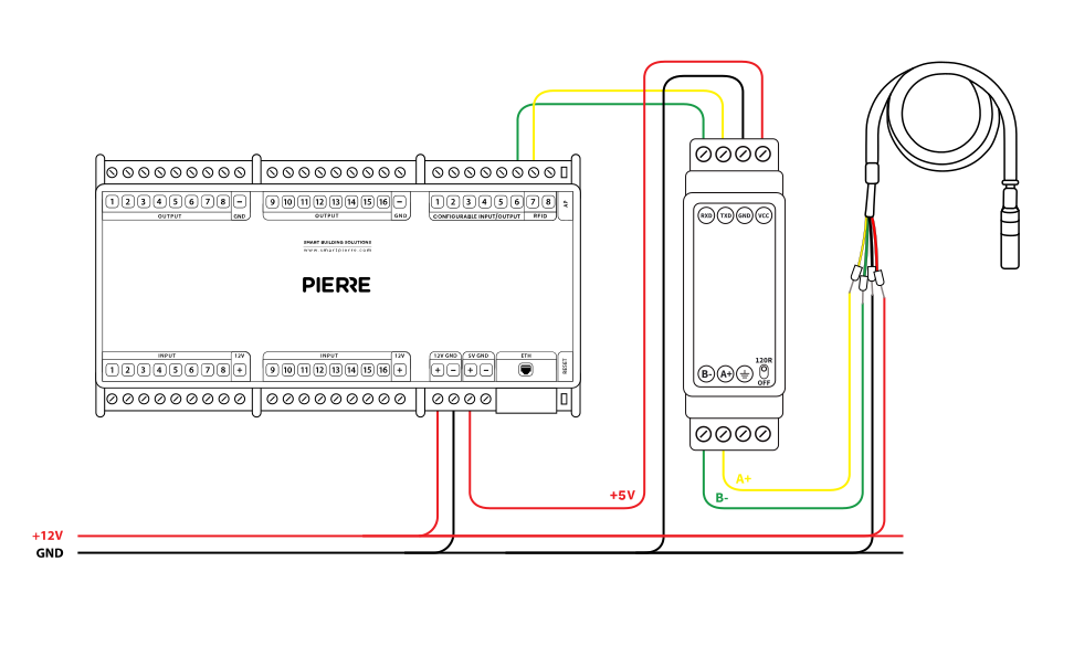
MODBUS Temp. and Humidity Sensor - Electric schemes
Cables - Temperature & Humidity modbus sensor
| Position | Wires | Diameter | Type | Comment |
|---|---|---|---|---|
| From PIERRE controller to TTL module | 4 | 0.25 mm² | Cat 5e U/UTP | +5V, GND, RX, TX |
| From TTL module to Temperature & Humidity sensor | 4 | 0.25 mm² | Cat 5e U/UTP | +12V, GND, A+, B- |
Schemes - Modbus fan-coil
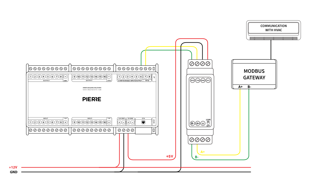
MODBUS Gateway - Electric schemes
Cables - Modbus fan-coil
| Position | Wires | Diameter | Type | Comment |
|---|---|---|---|---|
| From PIERRE controller to TTL module | 4 | 0.25 mm² | Cat 5e U/UTP | +5V, GND, RX, TX |
| From TTL module to Modbus gateway | 3 | 0.5 mm² | Shielded twisted pair, 2 × 2 | A+, B− on one pair; GND reference on the second pair |
Configuration in the PIERRE Partner App
Modbus RTU
- Open the controller and go to the Configurable I/O tab.
- Tap Add and choose Modbus RTU. Fill in Name and Role, and set baud rate, parity and data format to match the devices. Save.
- Open the Modbus RTU interface and add the devices. Choose a ready-made driver where one exists, otherwise Generic Modbus.
- For each device enter Name and Address (the unit ID from the device documentation).
- For a Generic Modbus device tap Add new I/O type, pick the I/O type, then map each field: register address, data type, transformation and access.
- Save. The device appears in the Smart PIERRE app as the chosen I/O type.
Modbus TCP
- Open the controller and go to the Services tab.
- Tap Add and choose Modbus TCP. Fill in Name, Role, and the IP address and port of the unit. Save.
- Add devices and map the fields as for Modbus RTU.
Operating the Equipment
Once configured, the unit is operated from the unit card in the Smart PIERRE app, from a PIERRE display or thermostat in the room, from scenarios (for example Leaving Home lowers every setpoint) and from automations (schedules, a window contact that stops heating).
Commissioning Test
- Bus check. Add one device first and confirm it shows live values before adding the rest of the line.
- Read. Open each device in the Partner app: room temperature, setpoint and fan speed show live values. An empty or zero field means a wrong address, register or line setting.
- Write. Change the setpoint in the Smart PIERRE app and confirm the unit follows. Wait for the next polling cycle before judging the read-back value.
- Read back. Change the setpoint on the unit or thermostat and confirm the app updates.
- Offline. Disconnect the internet and change the setpoint from a display. Regulation must continue.
Step-by-Step Example: Apartment with Modbus Thermostats and Underfloor Heating
Three rooms with underfloor heating, one PIERRE Modbus thermostat per room, one valve actuator per room on a controller output, and a circulation pump.
- Converter. TX on pin 1, RX on pin 7, wired and prepared as described in Wiring.
- Bus. Shielded 2 × 2 bus cable from the converter to thermostat 1, then 2, then 3: A+ and B− on one pair, GND reference on the second. Terminator at thermostat 3.
- Mains. L and N to each thermostat from the distribution board.
- Thermostats. In each thermostat menu set address 1, 2 and 3, and the same baud rate on all three.
- Outputs. Valve actuators on outputs 2 to 4, pump relay on output 5. Pins 1 and 7 are taken by the converter.
- Interface. Configurable I/O → Add → Modbus RTU, named Heating Bus, with the baud rate from step 4.
- Devices. Add three PIERRE Modbus thermostats – Living Room, Bedroom, Kitchen – with addresses 1, 2 and 3, each in its room group.
- Valves and pump. Add the valves on pins 2 to 4 and link each to its thermostat as the heating device. Add the pump on pin 5 with an automation: active when any valve is active.
- Test. Raise a room setpoint: the valve opens and the pump starts. Lower it: the valve closes, and the pump stops when the last valve closes.
Troubleshooting
| Symptom | Likely cause | What to check |
|---|---|---|
| No device answers | Wiring or line settings | A+/B− polarity; baud rate, parity and stop bits; converter RX on pin 7 or 8; termination DIP switch ON; the two 470 Ω resistors; only one master on the line. |
| One device does not answer, the others do | Address or settings of that device | Unique address; the device's line settings; its A+/B− wires. |
| Readings unstable, line drops out | Termination, topology or noise | 120 Ω at both ends; no branches; shield grounded at one end; reference ground conductor; line length. |
| Values are read but commands are ignored | Read-only register, or wrong register type for writing | Register table: Input registers cannot be written; coil or holding register; if the device accepts only function 16, use Holdings instead of Holding. |
| Value is 10× too high, or nonsense | Scaling, data type or word order | Divide / multiply; int16 or uint16; word swap for 32-bit values; swap mapping for mode values. |
| Value belongs to the neighbouring register | Address offset | Enter the address exactly as in the register table; PIERRE counts from 1. |
| Setpoint jumps back after a change | Polling too fast; unit reports the result in another register | Default polling interval; separate read-back register. |
| Daikin: new fan speed appears only after a delay | Normal: Daikin reports 10–15 s late | Wait at least 15 s before treating it as a fault. |
| AC: Off does not switch off, or On never arrives | Configuration model | On Daikin, value 0 of the mode selector means fan only, not off. Contact support. |
| AC: does not start from the app after the wall remote was used | Unit state changed locally | Send a clean Off first, then On. |
| AC: unit is off but still shows a mode | Normal: Daikin keeps the last mode | No action needed. |
| AC: one indoor unit works, another does not | Each indoor unit is configured separately | That unit's number and configuration. |
AC Integration
Air conditioners are the most demanding Modbus integration. The AC unit and the smart home speak different languages: the Modbus gateway is the interpreter, the PIERRE configuration is the dictionary, and every AC type needs its own dictionary. It does not depend only on PIERRE: the unit, the gateway and the documentation come from third parties, and some systems cannot be integrated at all.
An AC integration is therefore taken on only after a site survey, an engineering assessment and a test on a real unit, and nothing is guaranteed before that test.
Steps
- Site survey. Answer every question on the checklist below. A missing item means the integration cannot be assessed yet.
- Engineering assessment by PIERRE. If the system cannot be integrated, the process stops here.
- Test on a real unit. The integration is confirmed only when the test passes on the installed system.
- Handover.
Site Survey Checklist
- AC brand and exact model.
- Is there a Modbus gateway, or can one be fitted, and which model.
- How many indoor units, and do all of them need control.
- Will the wall remote stay in use.
- The manufacturer's address table for that exact gateway model is in hand.
- Line settings and indoor unit numbers are known.
- A powered, reachable unit is available for testing.
Technical Points
- The register table that counts is the one of the gateway model, not of the AC unit.
- Every indoor unit is a separate device with its own number and configuration.
- If the wall remote stays in use, the unit can change state without the controller; the app shows it after the next poll.
- Unit-specific behaviour, such as the Daikin delays, is listed in Troubleshooting.
When You Contact PIERRE Support
Send with every request:
- Brand, model and gateway model.
- The indoor unit's number or name.
- What the app shows, and what the wall remote shows.
- What the customer pressed, and when (date and time).
- Whether the wall remote was used in the meantime.
FAQ
No, a classic thermostat is not necessary. Instead, a temperature sensor integrated with the PIERRE system can monitor the room’s temperature and manage the heating/cooling devices accordingly.
Yes, PIERRE offers its own smart thermostats, which can be found in the thermostat product category.
Yes, you can replace an old thermostat with a PIERRE display, as long as the display includes a temperature sensor for temperature monitoring.
Yes, most PIERRE displays have built-in temperature sensors and can control heating/cooling systems just like a thermostat. All displays have relays that can send signals to heating/cooling devices to turn them on or off.
Heat meters with an M-Bus interface are read through an Intesis M-Bus to Modbus gateway connected to a PIERRE Pro controller. The meters are wired to the gateway's M-Bus (a shared two-wire bus) and the controller reads them over Modbus RTU.
Yes, you can control the temperature room by room.
The circulation pump’s operation is based on automation, so if the valve in any apartment’s floor heating system is activated, it simultaneously activates the circulation pump. If separate control is needed, it can only be handled locally within the apartment.
Yes, per manifold: an automation opens the valve when the room temperature drops below the set point and starts the pump once the valve is open (or after a short delay).
The heat pump can be controlled by PIERRE in two ways: • Potential-free contacts: one contact switches winter/summer mode, another starts and stops the heat pump. • Modbus RTU: consult the manufacturer or distributor in advance about the Modbus register addresses and documentation for the heat pump model.
The motorized valves for underfloor heating zones can be controlled without any issues by the PIERRE system, whether they are On-Off or 0-10V valves. In the mechanical room, the PIERRE system handles the following controls: winter-summer mode switching via a potential-free contact, circulation pump control, hot water circulation pump control, and 0-10V mixing valve control with supply water temperature measurement.