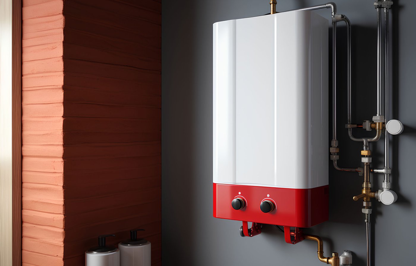
Solution - Valve Control
Description
Valve Types Supported by PIERRE
On/Off Valves
The most common valve type used in smart home installations. These valves operate in a simple open or closed state and are typically used for:
-
Main water shut-off
-
Flood protection
-
Irrigation systems
-
Floor/ceiling heating/cooling zone control
-
Fan coil control
On/Off valves can be controlled through relay outputs or SSR outputs, depending on the valve specifications.
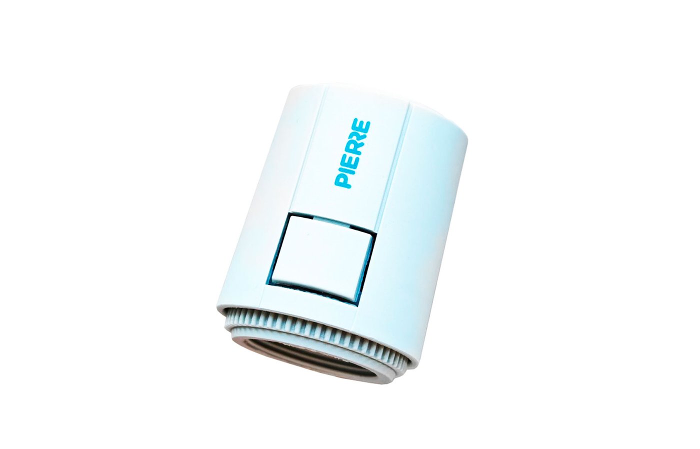
Thermoelectric Actuators
Thermoelectric actuators are widely used in underfloor heating and cooling systems. They operate by heating an internal element which gradually opens or closes the valve.
Typical characteristics:
-
24V AC/DC or 230V AC operation
-
Available in Normally Closed (NC) and Normally Open (NO) versions
-
Slow opening and closing operation
-
Low power consumption
These actuators are ideal for zone-based climate control applications.
Motorized Valves
Motorized valves use an electric motor to precisely open and close the valve.
Typical applications include:
-
Main water supply control
-
Heating and cooling systems
-
Mixing valves
-
Energy management systems
Proportional (PID-Controlled) Valves
For advanced HVAC applications, PIERRE can control proportional valves using analog outputs and PID algorithms.
These valves allow continuous position adjustment rather than simple open/close operation.
Benefits include:
-
Precise temperature regulation
-
Improved energy efficiency
-
Reduced temperature fluctuations
-
Optimized heating and cooling performance
Control signals include:
-
0–10V
Common applications:
-
Mixing valves
-
Chilled water systems
-
Hydronic heating systems
-
Air handling units (AHU)
-
Commercial HVAC installations
Low-Voltage Valves
Many modern valves operate on low-voltage power supplies, typically:
-
12V DC
-
24V DC
-
24V AC
These valves are commonly used where increased electrical safety or integration with building automation systems is required.
High-Voltage Valves
High-voltage valves are typically powered by:
-
110V AC
-
230V AC
They are commonly used for:
-
Main water shut-off systems
-
Industrial water control
-
Large residential installations
-
Commercial buildings
0–10 V Extender: suitable for controlling dimmable lights, fan-coil units, valves/actuators, and other 0–10 V controlled devices, provided that the device’s 0–10 V control input has a maximum short-circuit current of 1 mA. In other words, it is intended for low-current 0–10 V control signals, not for powering a load directly. If the controlled device sources more than 1 mA into the 0–10 V control line, it should not be connected directly to the extender.
Schemes - on/off valve
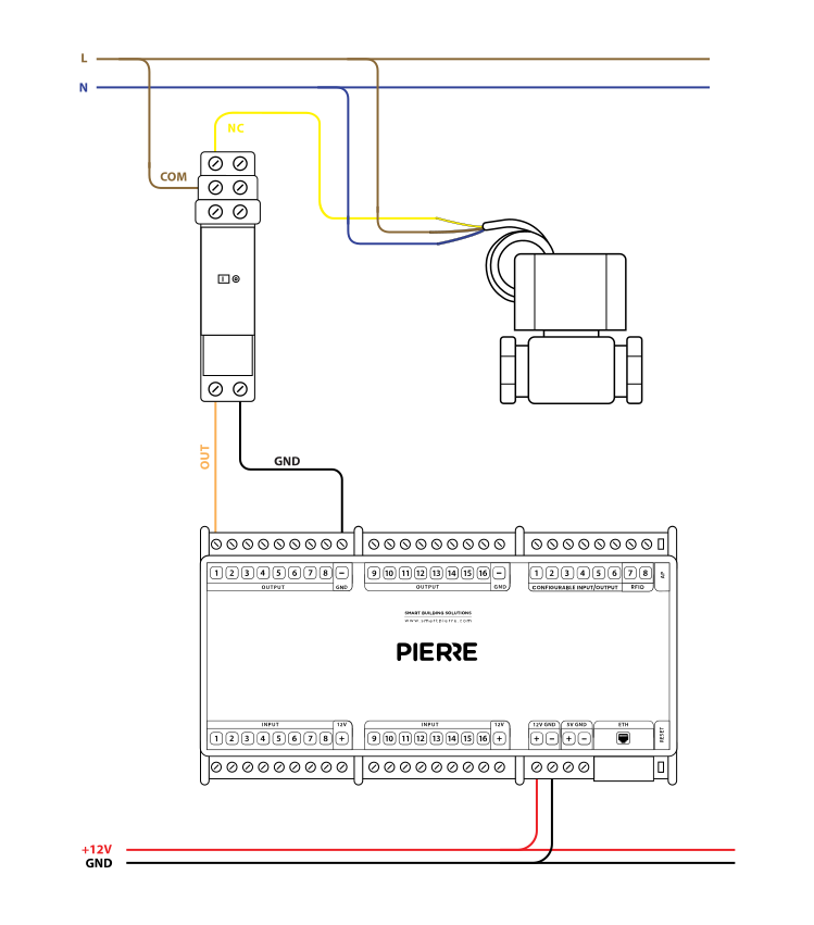
Wiring Water Valve in the PIERRE smart home system - Electric schemes
Schemes - Thermoelectric actuator
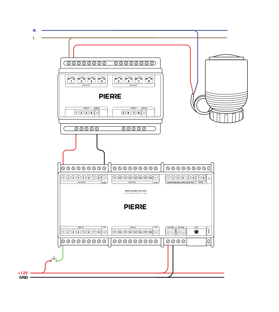
Wiring Electric Valve 230 V - Electric schemes
Schemes - PID regulated valve - 0-10V Extender is required
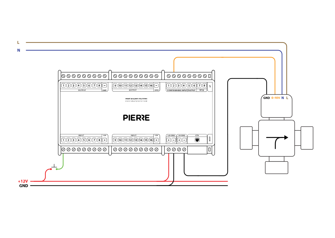
Wiring PID regulated Valve - Electric schemes
Schemes - Motorized valve
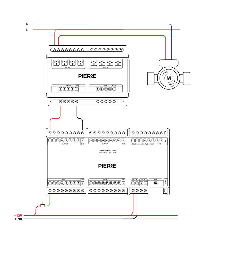
Schemes - Low-voltage valve
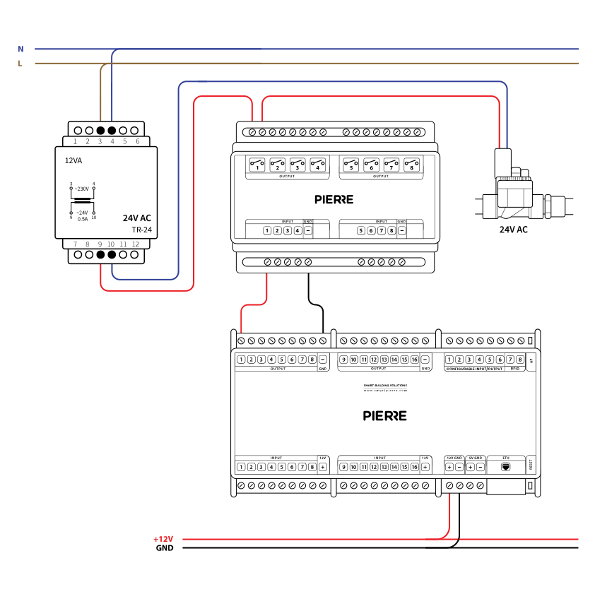
Cables
| Position | Wires | Diameter | Type | Comment |
|---|---|---|---|---|
| From relay to Valve | 2 or 3 or 4 | 1.5 mm² | NYM-O | L, N (L1 or GND, 0-10V) |
| From PIERRE Controller to relay | 2 | 0.75 mm² | H07V-K | GND, OUTPUT |
Troubleshooting
If not, the fault is not in PIERRE. Check that the device is wired correctly and has power before going any further.
Green – Online: the controller is connected to the network and operating normally. Red – Offline: the controller is disconnected from the network, or there is no internet access. White – Commissioning: the controller has started in commissioning mode and is waiting to be commissioned. Light blue – AP mode: the controller is broadcasting its own network for setup or configuration. Dark blue – Selected in the app: the controller is currently selected in the PIERRE Partner app, which helps you identify the physical controller in the cabinet. Purple – Searching for IP address: the controller is waiting to receive an IP address from the router. Orange – Firmware update: a firmware update is in progress; do not power off the controller while the LED is orange.
If not: Add it in the PIERRE Partner application.
If not: check the polarity of the GND and OUTPUT wires at the relay coil; they may be reversed. To rule out a relay fault, feed 12 V DC from the power supply directly to the relay coil input instead of the controller output.
If not, check every connection on the relay: is the line (L) connected, and are the right wires on the relay terminals?
Yes, an electric valve can always be added later, but it will require running the necessary power lines to the installation point.