Solution - ON/OFF Light control
Description
PIERRE Pro controls lighting over hardwired circuits. Each switched group runs on its own cable to a relay in the distribution board, driven by a controller output. The lamp and luminaire itself does not need to be a smart device; any standard fitting can be controlled this way.
What You Can Control
- On/off circuits, switched through a relay.
- Several independent zones in one installation, each on its own output.
Operating the Lighting
- From the dry-contact push button positions wired to the controller inputs.
- From the Smart PIERRE app.
- From scenarios, which set several circuits at once.
- From automation: a schedule, a motion sensor, a brightness reading, or a timeout that switches the light off after a set time.
The buttons, the automations and the timeouts run inside the controller, so they keep working when the internet connection is down. Only the app, scenarios started from the cloud and push notifications need the connection.
What You Need
- PIERRE Pro or Lite Controller with one free output per lighting circuit and o position.
- Relay, one relay per circuit.
- 12 V DC power supply for the controller and the relay coils.
- Dry contact (potential-free) momentary push buttons for the wall positions. The button must be a simple normally-open contact with no voltage of its own. The controller reads a press, a hold or a double press.
Wiring
Each circuit needs three runs:
- Connect +12 V and GND to both the relay and the controller. They must share a common ground.
- Connect each controller output to the matching relay input.
- Connect Live (L) to the COM terminal of the relay. Connect the NO (normally ohen the relay is activated, power flows from COM to NO and the light is on.
- Bring the neutral to the light directly from the distribution board.
- Wire every push button back to the controller: +12 V out to the button, the sroller input.
Planning Notes
- Check the load of each circuit against the rating of the relay. Split heavy circuits across two relays rather than overloading one.
- One circuit per output. Lights that must always switch together can share a relay; lights that must ever be controlled separately need separate outputs.
- Plan one controller input per wall position. One button can carry three actions (tap, hold, double press), so a single button can control up to three things, or different outputs of controller.
- Label each run with the identifier used in the electrical project; the same identifier is entered in the app.
Configuration
Both steps are done in the PIERRE Partner application.
Add the light:
- Open the controller.
- Go to Outputs and tap Add.
- Choose Light as the type.
- Fill in Name, Group, Role and Pin. Pin is the controller output wired to thedentifier from the electrical project if used.
- Submit and save.
Add the wall switch and link it to the light:
- Open the controller.
- Go to Inputs and tap Add.
- Choose Button as the type.
- Fill in Name, Role and Pin. Pin is the controller input the button is wired
- Open the button. It shows three actions: Tap, Hold and Double.
- Open Tap. In Toggle I/O choose the light. Toggle switches the light from its current state to the opposite one. Save.
- Optionally repeat for Hold and Double with other lights or scenarios.
Add automation if wanted: open the light, choose Automation, then New Time Conding I/O for a motion sensor or brightness sensor. A timeout can be set so the
light switches off by itself after the chosen time.
Testing
- Press the wall button. The relay clicks and the light comes on. Press again
- Switch the light from the Smart PIERRE app. The card shows the same state as the wall switch produced.
- Disconnect the internet and press the wall button again. The light must stilcircuit is handled locally by the controller.
Step-by-Step Example: Kitchen Ceiling Light with Two Wall Positions
A kitchen has one ceiling light circuit and two door positions where the custom
- In the distribution board, connect controller output 1 to the coil input of relay 1. Connect +12 V and GND from the power supply to the controller and to the relay.
- Wire L from the lighting MCB to COM of relay 1, and NO of relay 1 to the ceiling light on 1.5 mm² NYM-O. Take N to the light directly.
- Run one Cat 5e cable to each door position. At each button, connect +12 V toto controller input 1 and input 2 respectively.
- In the Partner app open the controller, Outputs, Add, Light. Name it Kitchen Ceiling, choose the Kitchen group and role, Pin: output 1. Save.
- Inputs, Add, Button. Name it Kitchen Door 1, Pin: input 1. Save. Open it, Ta Ceiling. Save.
- Repeat step 5 for Kitchen Door 2 on input 2.
- Test both buttons and the app card. Each press toggles the light regardless .
Variant: Hold for a Second Light
If the kitchen also has under-cabinet lights on output 2, add them as a second ttons to toggle Under-cabinet. A short press then controls the ceiling light, along press the cabinet lights, with no extra wall positions.
Schemes
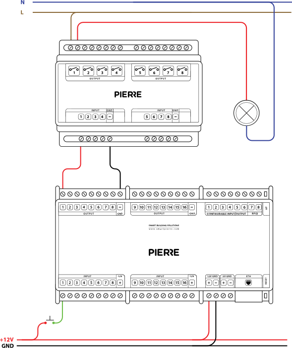
Lights Control - Electric schemes
Cables
| Position | Wires | Diameter | Type | Comment |
|---|---|---|---|---|
| From PIERRE Controller to Relay | 2 | 0.75 mm² | H07V-K | GND, OUTPUT |
| From Relay to Light | 2 | 1.5 mm² | NYM-O | L, N |
| From Push button to PIERRE Controller | 2 | cat.5 | UTP | +12V, SIGNAL |
Troubleshooting
Green – Online: the controller is connected to the network and operating normally. Red – Offline: the controller is disconnected from the network, or there is no internet access. White – Commissioning: the controller has started in commissioning mode and is waiting to be commissioned. Light blue – AP mode: the controller is broadcasting its own network for setup or configuration. Dark blue – Selected in the app: the controller is currently selected in the PIERRE Partner app, which helps you identify the physical controller in the cabinet. Purple – Searching for IP address: the controller is waiting to receive an IP address from the router. Orange – Firmware update: a firmware update is in progress; do not power off the controller while the LED is orange.
If not, add it in the PIERRE Partner app. Also check that the push button is assigned to the output it should control (lamp, gate, …).
If not: check the polarity of the GND and OUTPUT wires at the relay coil; they may be reversed. To rule out a relay fault, feed 12 V DC from the power supply directly to the relay coil input instead of the controller output.
If not, check every connection on the relay: is the line (L) connected, and are the right wires on the relay terminals?
If the power goes out, smart devices will retain their last state and resume functionality when power is restored. For critical devices, battery backups can be used to maintain operation during an outage.
The PIERRE system uses star wiring: every device to be controlled must be wired back to a central point — the distribution box of the PIERRE Controllers. This box can be separate from the high-voltage wiring or combined with it. In larger installations a separate star point per floor is common, with each floor having its own PIERRE distribution box. All of these boxes are connected to the network, which keeps the whole system integrated.
Every fixture that must be switched separately needs its own cable. Lights on the same circuit can be wired together and controlled by a single switch. All cables — including the switch cables — must run to the PIERRE distribution box.