
Solution - Push Button Control
Description
The PIERRE PRO system uses momentary push buttons as physical wall controls. Standard latching or toggle switches are not used for direct PIERRE PRO input control.
When the push button is pressed, it sends the 12 V signal supplied by the PIERRE Controller back to the corresponding Controller input. The Controller detects the button press and performs the function configured for that input.
The physical push button is therefore used only as an input device. The actual controlled function is defined in the PIERRE system.
Wiring Principle
Push buttons in a PIERRE PRO installation require star wiring.
Each push-button connection is wired directly from the wall switch location back to the PIERRE Controller. The push button is not wired directly to the lighting circuit or other controlled load.
The basic principle is:
PIERRE Controller 12 V → Push Button → PIERRE Controller Input
When the button is pressed, the contact closes and sends the 12 V signal back to the corresponding Controller input.
The lighting circuit or other controlled device is wired separately to the appropriate PIERRE Controller output.
Single Push Button
A standard single-pole momentary push button requires a 2-core cable between the PIERRE Controller and the push button.
-
One conductor carries 12 V from the PIERRE Controller to the push button.
-
The second conductor returns the switched 12 V signal to the appropriate PIERRE Controller input when the button is pressed.
This provides one independent push-button command.
Multiple Push Buttons at One Location
Where several push-button contacts are installed at the same wall location, a multi-core cable can be used instead of separate 2-core cables for every button.
Suitable cabling can include, for example:
-
multi-core control cable, such as YS(L)Y,
-
Cat.5 UTP or other suitable multi-core cable.
One conductor can be used as the common 12 V supply, while the remaining conductors return the individual switched signals to separate PIERRE Controller inputs.
Example with UTP Cable
A standard UTP cable contains 8 conductors (4 twisted pairs).
One conductor can carry the common 12 V supply to the push buttons, leaving 7 conductors available as individual return signals.
Therefore, one 8-core UTP cable can provide up to 7 separate push-button inputs from one switch location:
-
1 conductor – common 12 V supply,
-
7 conductors – up to 7 individual switched 12 V return signals.
Each return conductor is connected to a separate PIERRE Controller input.
This allows up to seven different lighting circuits or other PIERRE functions to be controlled from one multi-button wall location using a single UTP cable.
Configuration
Once connected, each push-button input can be configured in the PIERRE Partner application and assigned to the required I/O or function.
Depending on the configuration, a push button can support:
-
Tap – single press,
-
Hold – long press,
-
Double – double press.
These interactions can be configured to perform different functions.
Applications
Push buttons can be used to control:
-
lighting,
-
dimmable lighting,
-
blinds, shutters and curtains,
-
Doors and Gates,
-
Scenes,
-
relays and other configured outputs,
-
other functions available in the PIERRE system.
A physical push button is therefore not permanently tied to a specific lighting circuit. Its function is determined by the PIERRE configuration.
Automation
Push-button events can also be used in PIERRE Automations.
For example, a button press can:
-
activate a Scene,
-
control multiple I/Os,
-
trigger another configured action,
-
start an Automation.
Technical Notes
-
PIERRE PRO requires momentary push buttons for direct wall-switch input control. Standard latching or toggle switches must not be used for this purpose.
-
Push buttons require star wiring back to the PIERRE Controller.
-
The push button is wired to the Controller input, not directly to the controlled lighting circuit or load.
-
The PIERRE Controller provides the 12 V signal, which is returned to the appropriate input when the button is pressed.
-
A single push-button contact requires 2 conductors.
-
Multiple push buttons at the same location can share one common 12 V conductor and use separate return conductors for each input.
-
An 8-core UTP cable can provide one common 12 V conductor and up to seven individual push-button return signals.
-
Never connect 230 V mains voltage to a PIERRE Controller input.
-
Power/load wiring and push-button input wiring are separate parts of the installation.
-
Wiring must follow the applicable PIERRE wiring documentation and electrical installation requirements.
Schemes - 1 gang button
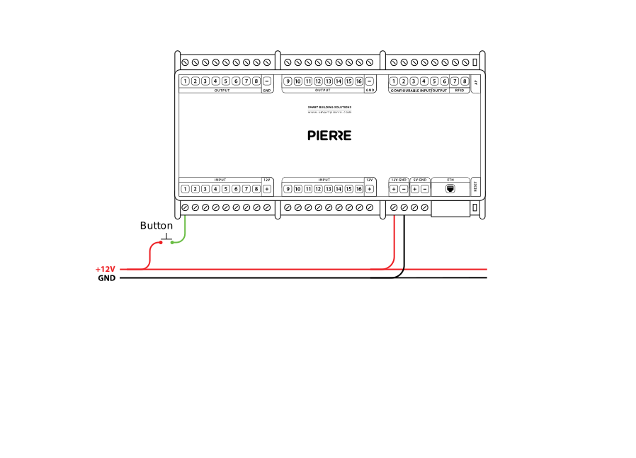
Button - wiring - Electric schemes
Cables - 1 gang button
| Position | Wires | Diameter | Type | Comment |
|---|---|---|---|---|
| From Push button to PIERRE | 2 | 0.25 mm² | Cat5 UTP | +12V, SIGNAL |
Schemes - 4 gang button
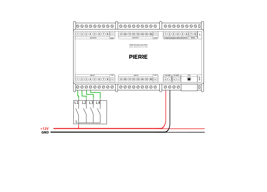
Cables - 4 gang button
| position | Wires | diameter | type | comment |
|---|---|---|---|---|
| From Push button to PIERRE | 5 | 0.25 mm² | Cat5 UTP | +12V, SIGNAL1-4 |
Troubleshooting
Green – Online: the controller is connected to the network and operating normally. Red – Offline: the controller is disconnected from the network, or there is no internet access. White – Commissioning: the controller has started in commissioning mode and is waiting to be commissioned. Light blue – AP mode: the controller is broadcasting its own network for setup or configuration. Dark blue – Selected in the app: the controller is currently selected in the PIERRE Partner app, which helps you identify the physical controller in the cabinet. Purple – Searching for IP address: the controller is waiting to receive an IP address from the router. Orange – Firmware update: a firmware update is in progress; do not power off the controller while the LED is orange.
If not, add it in the PIERRE Partner app. Also check that the push button is assigned to the output it should control (lamp, gate, …).
If not, wire it as shown in the diagram. To rule out the device and its cable, briefly bridge the controller's 12 V output to the input the device is wired to. If the input turns green in the app (or the connected output switches), the controller and the input are fine and the fault is in the device or its cable.
If not, the fault is in the device or its supply, not in PIERRE. Check that the lamp, door or other device is powered and works when switched directly.
The PIERRE system uses star wiring: every device to be controlled must be wired back to a central point — the distribution box of the PIERRE Controllers. This box can be separate from the high-voltage wiring or combined with it. In larger installations a separate star point per floor is common, with each floor having its own PIERRE distribution box. All of these boxes are connected to the network, which keeps the whole system integrated.