Solution - Dimmable Light Control
Description
PIERRE Pro dims lighting over hardwired circuits. The controller sets the brightness on one of its configurable I/O pins, and a dimmer, driver or adapter turns that signal into the power the luminaire needs. PIERRE works with regular bulbs, LED lamps and LED strips, at 230 V and at low voltage such as 12 V or 24 V. The light source itself must be dimmable. If the LED specification does not state that the lamp is dimmable, assume it is not.
What You Can Control
- PWM dimmed circuits, most often 12 V or 24 V LED strips and LED lamps driven directly from the controller signal.
- 0–10 V dimmed circuits, such as LED drivers and ballasts with a 0–10 V control input, through the PIERRE Pro 0–10 V Extender.
- Phase-cut dimmed 230 V circuits, such as dimmable 230 V LED lamps, halogen and incandescent, through the Dimmer Slave 0–10 V driven by the extender.
- Several independent dimmed zones in one installation, each on its own configurable I/O.
On/off circuits switched through a relay are covered in the On/Off Light Control lesson. RGB and RGBW strips are a separate I/O type with their own lesson.
Operating the Lighting
- From the wall push buttons wired to the controller inputs. Each button action can set a different brightness, for example tap to 100 %, double tap to 60 %, hold to 20 %.
- From the Smart PIERRE app, with the on/off toggle and the intensity slider.
- From scenarios, which set several circuits to chosen levels at once.
- From automation: a schedule, a motion sensor, a brightness reading, or a timeout that switches the light off after a set time.
The wall buttons, the automations and the timeouts run inside the controller, so they keep working when the internet connection is down. Only the app, scenarios started from the cloud and push notifications need the connection.
Dimming Methods
- PWM dimming – common for LED. The light is switched on and off at high frequency and the pulse width sets the brightness. The controller produces this signal itself on a configurable I/O.
- 0–10 V dimming – used for fluorescent ballasts and many LED drivers. A 0–10 V signal goes to the driver, which varies the brightness. The controller does not output 0–10 V directly; the PIERRE Pro 0–10 V Extender converts the PWM signal.
- Phase-cut dimming – used for incandescent, halogen and some 230 V LED lamps. It cuts part of the AC waveform and comes in leading-edge and trailing-edge variants. In the Pro system a phase-cut dimmer with a 0–10 V control input, the Dimmer Slave 0–10 V, is driven from the extender.
LED drivers. Constant-current drivers supply a fixed current and are dimmed by reducing that current. Constant-voltage drivers hold a fixed voltage and are dimmed by PWM or by current reduction. Check the driver and the lamp specification together: the dimmer, the driver and the light source all have to use the same method.
What You Need
- PIERRE Pro or Lite Controller with one free configurable I/O per dimmed circuit and one free input per wall button position.
- For PWM: a PWM-dimmable LED driver or PWM dimmer matched to the strip, plus a power supply sized to the total load of the strip.
- For 0–10 V: the PIERRE Pro 0–10 V Extender and a driver or ballast with a 0–10 V input.
- For phase-cut 230 V: the PIERRE Pro 0–10 V Extender and the Dimmer Slave 0–10 V.
- Dry contact (potential-free) momentary push buttons for the wall positions. The button must be a simple normally-open contact with no voltage of its own. Latching switches are not used; the controller reads a press, a hold or a double press.
- 12 V DC power supply for the controller.
Wiring
The wiring diagrams below show the three routes. The cable table lists every run.
- PWM. Connect the configurable I/O and GND of the controller to the signal and GND input of the PWM dimmer or driver. Connect the driver output to the LED strip on 0.75 mm² H07V-K. Feed the driver from its own power supply. Use a common ground between the controller and the dimmer.
- 0–10 V. Connect the configurable I/O and GND to the input of the 0–10 V Extender. Connect the extender output to the 0–10 V control input of the driver. Bring 230 V L and N to the driver on 1.5 mm² NYM-O.
- Phase-cut. Connect the configurable I/O and GND to the extender, the extender output to the 0–10 V input of the Dimmer Slave, and 230 V L and N to the Dimmer Slave. Connect the dimmed output of the Dimmer Slave to the lamp on 1.5 mm² NYM-O.
- Push buttons. Wire every button as a dry contact: +12 V from the controller to one terminal, the other terminal back to a controller input. Nothing else is connected to the button.
- Run the low-voltage signal cables on Cat 5e and keep them away from mains cables.
RGB modules. An RGB module is driven by direct PWM from the controller. The controller +5 V output and the RGB module IN input must be connected with a twisted pair; without a twisted pair the module does not work reliably. Check the strip length and specification to decide whether an RGB amplifier is needed.
0–10 V Extender limit. The extender is for dimmable lights, fan-coil units, valves, actuators and other 0–10 V controlled devices whose control input has a maximum short-circuit current of 1 mA. It carries a low-current control signal and does not power a load. A device that sources more than 1 mA into the 0–10 V line must not be connected directly to the extender.
Planning Notes
- Decide per circuit whether it is on/off or dimmed before the wiring is done. A dimmed circuit needs the signal run to the dimmer and, for 0–10 V and phase-cut, the extender in the board.
- Check the load of each circuit against the rating of the dimmer or driver. A phase-cut dimmer also has a minimum load; a single small LED lamp may flicker below it.
- The luminaire or its driver must state which dimming method it supports. Mixing methods on one circuit does not work.
- Match the power supply capacity to the total consumption of the connected strips. Long strips need feeding at intervals to avoid voltage drop.
- One circuit per configurable I/O. Lights that must always dim together can share a driver; lights that must ever be set separately need separate I/Os.
- Plan one controller input per wall position. One button carries three actions, so a single button can give three brightness levels.
- Choose dry contact push buttons at the design stage. The button is an on/off device, not a dimming device; the brightness levels are assigned to its actions in the app.
Configuration
All steps are done in the PIERRE Partner application.
Add the dimmable light:
- Open the controller.
- Go to Configurable I/O and tap Add.
- Choose Dimmable Light as the type.
- Fill in Name, Group, Role and Pin. Pin is the configurable I/O wired to the dimmer, driver or extender. Add a photo and the identifier from the electrical project if used.
- Submit and save.
Add the wall button and assign brightness levels:
- Open the controller, go to Inputs, tap Add and choose Button.
- Fill in Name, Role and Pin. Pin is the controller input the button is wired to. Save.
- Open the button. It shows three actions: Tap, Hold and Double.
- Open Tap, choose the dimmable light and set the action: Toggle switches between off and the last level, or choose a fixed intensity such as 100 %. Save.
- Repeat for Hold and Double with other levels, for example 20 % and 60 %.
Add automation if wanted: open the light, choose Automation, then New Time Condition for a schedule or Existing I/O for a motion or brightness sensor. A timeout can be set so the light switches off by itself after the chosen time.
Testing
- In the Smart PIERRE app, hold the light card and move the intensity slider. The light must follow smoothly from the lowest level to 100 % without flicker.
- Press the wall button. The light goes to the level assigned to Tap. Try Hold and Double.
- Disconnect the internet and press the wall button again. The light must still respond, which confirms the circuit is handled locally by the controller.
- If the light does not respond, check the polarity of GND and the configurable I/O, check that the light is added in the Partner app and that the button action points at it, and check that an intensity above zero is set. See the FAQ below.
Step-by-Step Example: Living Room LED Strip with One Wall Position
A living room has a 24 V dimmable LED strip under the ceiling cove and one wall position by the door.
- In the distribution board, fit the 24 V power supply and the PWM dimmer. Connect the power supply output to the dimmer supply input.
- Connect configurable I/O 1 and GND of the controller to the signal and GND input of the dimmer on Cat 5e.
- Connect the dimmer output to the strip on 0.75 mm² H07V-K. For a strip longer than 5 m, feed it from both ends.
- Run one Cat 5e cable to the wall position and fit a dry contact push button. Connect +12 V from the controller to one terminal and the other terminal back to controller input 1.
- In the Partner app open the controller, Configurable I/O, Add, Dimmable Light. Name it Living Room Cove, choose the Living Room group and role, Pin: configurable I/O 1. Save.
- Inputs, Add, Button. Name it Living Room Door, Pin: input 1. Save. Open it: Tap sets Living Room Cove to Toggle, Double sets it to 60 %, Hold sets it to 20 %. Save.
- Test the slider in the app, then the three button actions, then once more with the internet disconnected.
Variant: 230 V dimmable LED downlights. Fit the 0–10 V Extender and the Dimmer Slave 0–10 V in the board. Connect configurable I/O 1 and GND to the extender, the extender output to the Dimmer Slave 0–10 V input, 230 V L and N to the Dimmer Slave, and its dimmed output to the downlights on 1.5 mm² NYM-O. The app configuration is the same. Check that the total downlight load is above the minimum load of the Dimmer Slave.
Schemes - PWM dimming
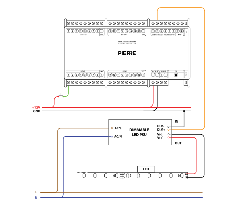
PWM Dimmable light - Electric schemes
Cables - PWM dimming
| position | wires | diameter | type | comment |
|---|---|---|---|---|
| From Pierre to Dimmable LED PSU | 2 | 0.75 mm² | H07V-K | PWM, GND |
| From Pierre to Push button | 2 | 0.5 mm² | H07V-K | +12V, IN |
| From Electric box to LED PSU | 2 | 1.5 mm² | H07V-K | L, N |
| From LED PSU to LED strip | 2 | 1.5 mm² | H07V-K | V+, V- |
Schemes - 0-10V dimming
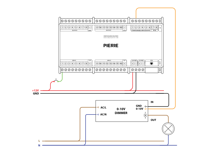
0-10V Dimmable light - Electric schemes
Cables - 0-10V dimming
| position | wires | diameter | type | comment |
|---|---|---|---|---|
| From Pierre to 0-10V dimmer | 2 | 0.5 mm² | H07V-K | 0-10V, GND |
| From Pierre to Push button | 2 | 0.5 mm² | H07V-K | +12V, IN |
| From Electric box to 0-10V dimmer | 2 | 1.5 mm² | H07V-K | L, N |
| From 0-10V dimmer to Bubl | 2 | 1.5 mm² | H07V-K | OUT, N |
Schemes - 0-10V extender
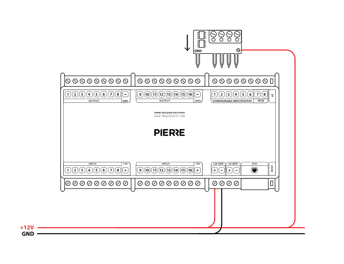
PWM to 0-10V adapter - Needed for 0-10V control - Electric schemes
Cables - 0-10V extender
| position | Wires | diameter | type | comment |
|---|---|---|---|---|
| From 0-10V extender to Pierre | 1 | 0.75 mm² | H07V-K | +12V |
| From 0-10V extender to Dimmable light | 2 | 0.5 mm² | H07V-K | 0-10V, GND |
Schemes - RGB lights
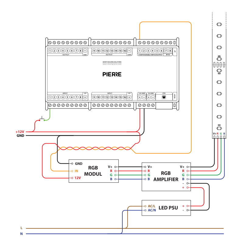
RGB Modul - The "+5V" and the RGB module input "IN" must be connected with a twisted pair; otherwise, it won't work. - Electric schemes
Cables
| Position | Wires | Diameter | Type | Comment |
|---|---|---|---|---|
| From Electric box to LED PSU | 2 | 1.5 mm² | H07V-K | L, N |
| From Pierre to RGB module | 3 | 0.75 mm² | H07V-K | PWM, +12V, GND |
| From RGB module to RGB amplifier | 4 | 0.75 mm² | H07V-K | V+, R, G, B |
| From Pierre to Push button | 2 | 0.5 mm² | H07V-K | +12V, SIGNAL |
| From RGB amplifier ro LED strip | 4 | 1.5 mm² | H07V-K | V+, R, G, B |
| From LED PSU to RGB amplifier | 2 | 1.5 mm² | H07V-K | 12V+, GND |
Troubleshooting
Green – Online: the controller is connected to the network and operating normally. Red – Offline: the controller is disconnected from the network, or there is no internet access. White – Commissioning: the controller has started in commissioning mode and is waiting to be commissioned. Light blue – AP mode: the controller is broadcasting its own network for setup or configuration. Dark blue – Selected in the app: the controller is currently selected in the PIERRE Partner app, which helps you identify the physical controller in the cabinet. Purple – Searching for IP address: the controller is waiting to receive an IP address from the router. Orange – Firmware update: a firmware update is in progress; do not power off the controller while the LED is orange.
If not: Check the polarity, maybe they are reversed.
If not, add it in the PIERRE Partner app. Also check that the push button is assigned to the output it should control (lamp, gate, …).
If not: Set higher intensity in the Smart PIERRE app - hold the I/O on the dashboard and set the slider higher.
If yes: Is the PWM power supply powerful enough for the consumption of the given LED strip? Check the wiring: DIM+ and DIM- are correctly connected to PIERRE controller?
If yes: Is the PIERRE Controller setup for 0-10V control on the specific PIN?
If the power goes out, smart devices will retain their last state and resume functionality when power is restored. For critical devices, battery backups can be used to maintain operation during an outage.
The PIERRE system uses star wiring: every device to be controlled must be wired back to a central point — the distribution box of the PIERRE Controllers. This box can be separate from the high-voltage wiring or combined with it. In larger installations a separate star point per floor is common, with each floor having its own PIERRE distribution box. All of these boxes are connected to the network, which keeps the whole system integrated.
Every fixture that must be switched separately needs its own cable. Lights on the same circuit can be wired together and controlled by a single switch. All cables — including the switch cables — must run to the PIERRE distribution box.
Yes, through the track's LED driver. Choose a 48 V driver with a 0–10 V or PWM dimming input and connect it to the controller (0–10 V on a configurable I/O, PWM on the dimmer output). Phase-cut dimming is also possible with a phase-dimmable driver.