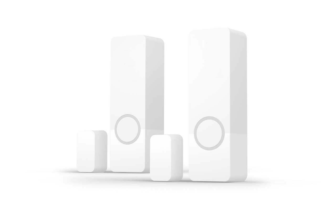
Solution - Contact Sensor
Description
A contact sensor reports whether an opening is open or closed — a door, window, gate, garage door or any other monitored opening. The system supports PIERRE contact sensors and compatible third-party sensors.
Electrical Requirements
- PIERRE contact sensors operate on a 12 VDC input circuit and connect directly to the controller inputs.
- A third-party sensor can be used if it provides a compatible dry-contact output and meets the electrical requirements of the controller inputs.
- Standard low-voltage wiring is used, run back to the controller input.
Configuration
Sensors are added and configured in the PIERRE Partner application. Once configured, native and third-party sensors behave identically in the system.
Status Monitoring
- Open and Closed states are reported to the system.
- The status is visible in the application and is available to automation logic.
Automation
A contact sensor can be used as a trigger for:
- Alarm activation and monitoring.
- Heating and cooling control based on window or door status.
- Lighting triggered by an opening.
- Notifications and alerts.
- Scene activation and occupancy-based automation.
The status can be combined with schedules, user presence and other sensors to build more specific rules.
Technical Notes
- Check the sensor's rest state before configuring: a normally-closed sensor reports the opposite of a normally-open one, and getting this wrong inverts every rule built on it.
- Keep the magnet gap within the manufacturer's specification. On a door that settles over time the gap grows and the sensor starts reporting open.
- Recessed sensors have to be planned before the frame is fitted; surface sensors can be added later.
- Test every sensor physically at handover, opening and closing the actual door or window.
Schemes
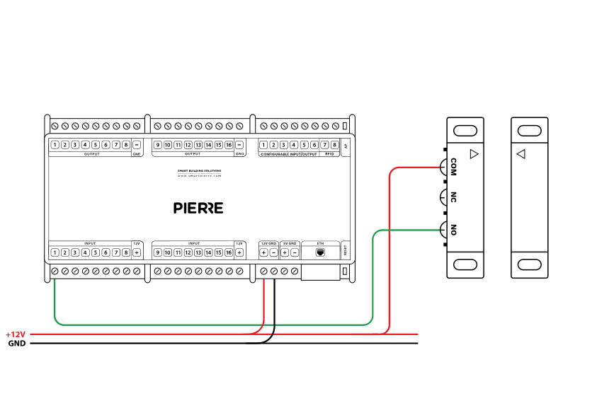
Wiring third party contact sensor in PIERRE smart home system - Electric schemes
Schemes
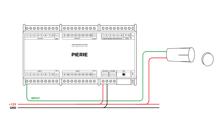
Wiring third party contact sensor for windows in PIERRE smart home system - Electric schemes
Cables
| Position | Wires | Diameter | Type | Comment |
|---|---|---|---|---|
| From Contact sensor to PIERRE | 2 | cat.5 | UTP | +12V, INPUT |
Troubleshooting
Green – Online: the controller is connected to the network and operating normally. Red – Offline: the controller is disconnected from the network, or there is no internet access. White – Commissioning: the controller has started in commissioning mode and is waiting to be commissioned. Light blue – AP mode: the controller is broadcasting its own network for setup or configuration. Dark blue – Selected in the app: the controller is currently selected in the PIERRE Partner app, which helps you identify the physical controller in the cabinet. Purple – Searching for IP address: the controller is waiting to receive an IP address from the router. Orange – Firmware update: a firmware update is in progress; do not power off the controller while the LED is orange.
If not: Add it in the PIERRE Partner app.
If not: Give it a try. If the sensor has been newly added, it needs a state change.
If not, wire it as shown in the diagram. To rule out the device and its cable, briefly bridge the controller's 12 V output to the input the device is wired to. If the input turns green in the app (or the connected output switches), the controller and the input are fine and the fault is in the device or its cable.
When an input triggers an output — for example a motion sensor that switches a lamp — add both to the same controller. This gives the fastest response.
Pro contact sensors are typically installed during construction, as they require wiring within the walls. Wave contact sensors can be installed later, as they are wireless and easy to place.
The contact sensor should be installed so that the sensor and magnet are aligned when the door or window is closed. For windows, placing the sensor on the top allows it to detect even when the window is tilted open.
Each sensor (motion, light, contact, etc.) is wired individually to the PIERRE distribution cabinet in a star topology. • INPUT 12–24 V – 12 V DC from the PIERRE controller • GND – GND from the PIERRE controller • Switch K1 – to INPUT 12–24 V • Switch K2 – to a digital input of the PIERRE controller