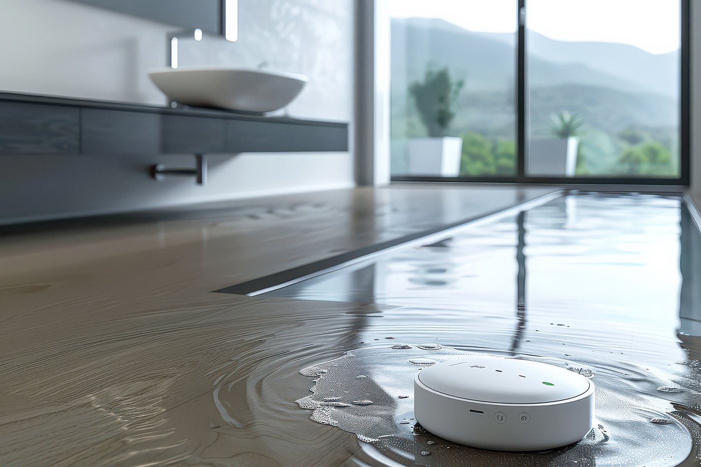
Solution - Leak Sensor
Description
A leak sensor detects water or excessive moisture at a specific point and reports it to the controller, which can raise a notification and trigger a scenario.
Connection
- The sensor is wired to a controller input.
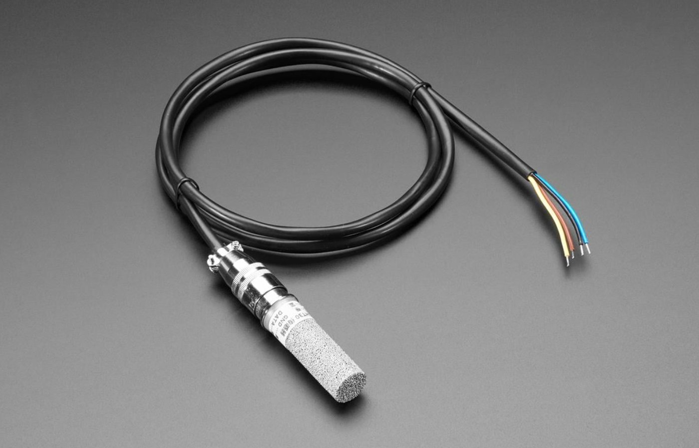
- Most third-party leak sensors provide a dry contact that closes when water is detected — this is the type that connects directly.
- Keep the cable run away from mains wiring.
What It Can Trigger
- A notification in the app.
- Closing a motorised water valve on the main supply.
- Switching off a connected appliance circuit.
Technical Notes
- Place the probe at the lowest point where water would collect — under the boiler, behind the washing machine, next to the manifold.
- The probe must sit on the floor. A sensor mounted on the wall above the floor detects nothing.
- A leak sensor is only useful if something acts on it. Where the risk is real, pair it with a motorised valve on the incoming water line.
- Test the sensor at handover with a wet cloth, and confirm both the notification and the valve action.
Schemes
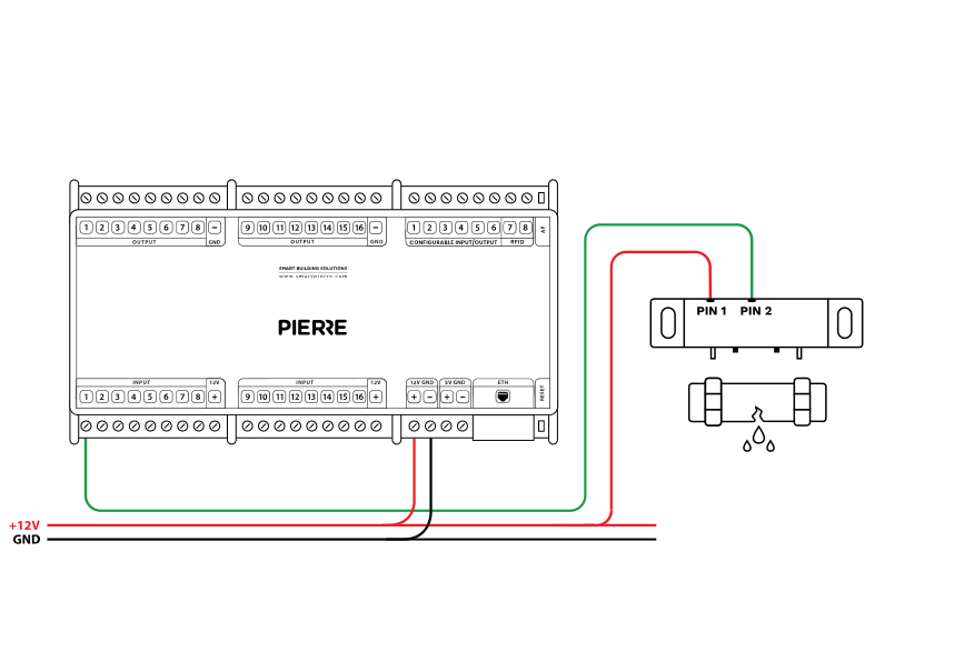
Wiring third party Flood sensor in PIERRE smart home system - Electric schemes
| Position | Wires | Diameter | Type | Comment |
|---|---|---|---|---|
| From Flood sensor to PIERRE | 2 | cat.5 | UTP | +12V, SIGNAL (GND) |
Schemes
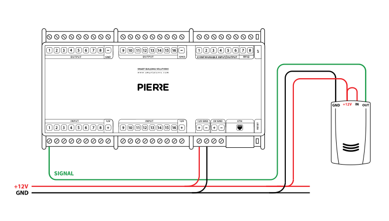
Wiring third party Floods sensors in PIERRE smart home system - Electric schemes
Cables
| Position | Wires | Diameter | Type | Comment |
|---|---|---|---|---|
| From Flood sensor to PIERRE | 3 | cat.5 | UTP | +12V, SIGNAL (GND) |
Troubleshooting
Check the polarity of the sensor wiring first. Then check whether the sensor reports a permanent leak: a wet, dirty or shorted probe keeps the input active. Dry and clean the probe and test again.
Green – Online: the controller is connected to the network and operating normally. Red – Offline: the controller is disconnected from the network, or there is no internet access. White – Commissioning: the controller has started in commissioning mode and is waiting to be commissioned. Light blue – AP mode: the controller is broadcasting its own network for setup or configuration. Dark blue – Selected in the app: the controller is currently selected in the PIERRE Partner app, which helps you identify the physical controller in the cabinet. Purple – Searching for IP address: the controller is waiting to receive an IP address from the router. Orange – Firmware update: a firmware update is in progress; do not power off the controller while the LED is orange.
If not, add it in the PIERRE Partner app.
If not: Give it a try. If the sensor has been newly added, it needs a state change.
If not, wire it as shown in the diagram. To rule out the device and its cable, briefly bridge the controller's 12 V output to the input the device is wired to. If the input turns green in the app (or the connected output switches), the controller and the input are fine and the fault is in the device or its cable.
When an input triggers an output — for example a motion sensor that switches a lamp — add both to the same controller. This gives the fastest response.
The leak sensor should be placed near water sources like sinks, water heaters, or pipes, so it can detect leaks quickly.
Each sensor (motion, light, contact, etc.) is wired individually to the PIERRE distribution cabinet in a star topology. • INPUT 12–24 V – 12 V DC from the PIERRE controller • GND – GND from the PIERRE controller • Switch K1 – to INPUT 12–24 V • Switch K2 – to a digital input of the PIERRE controller