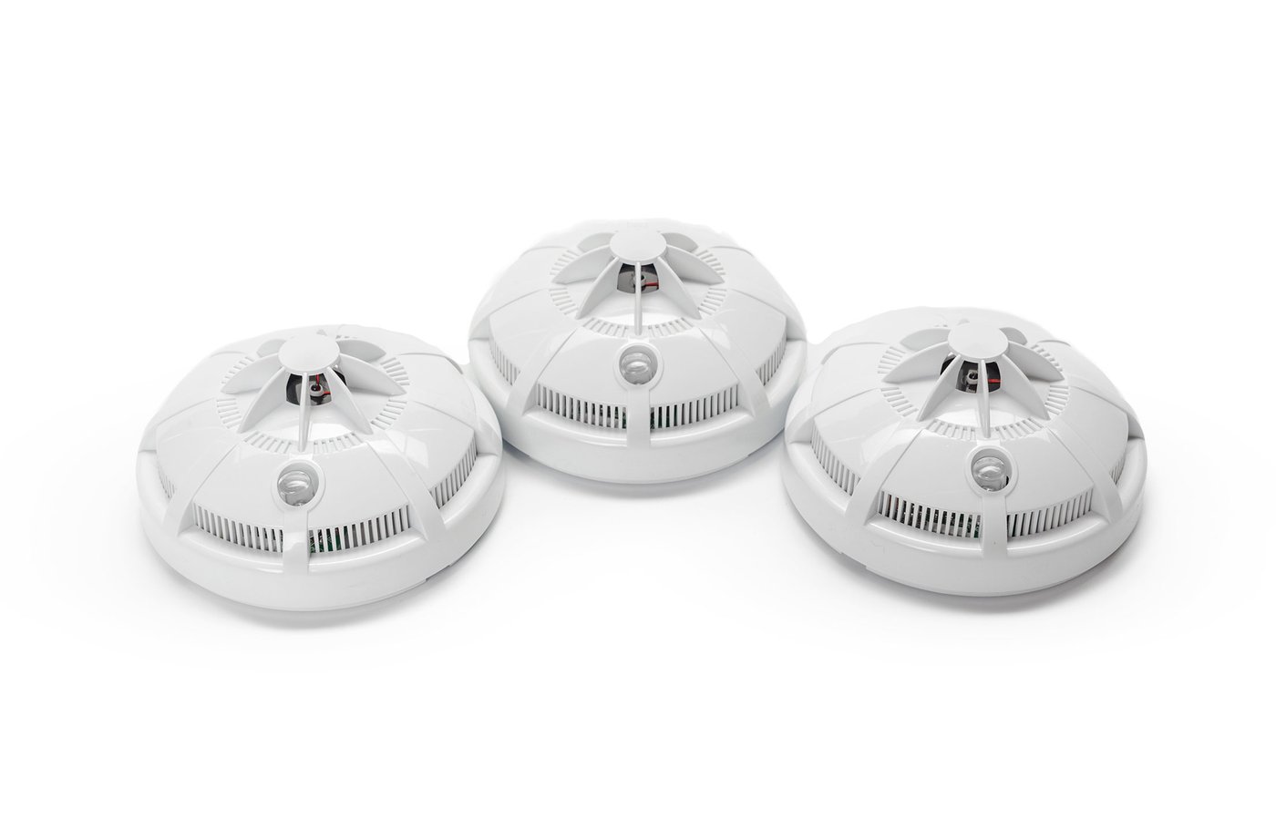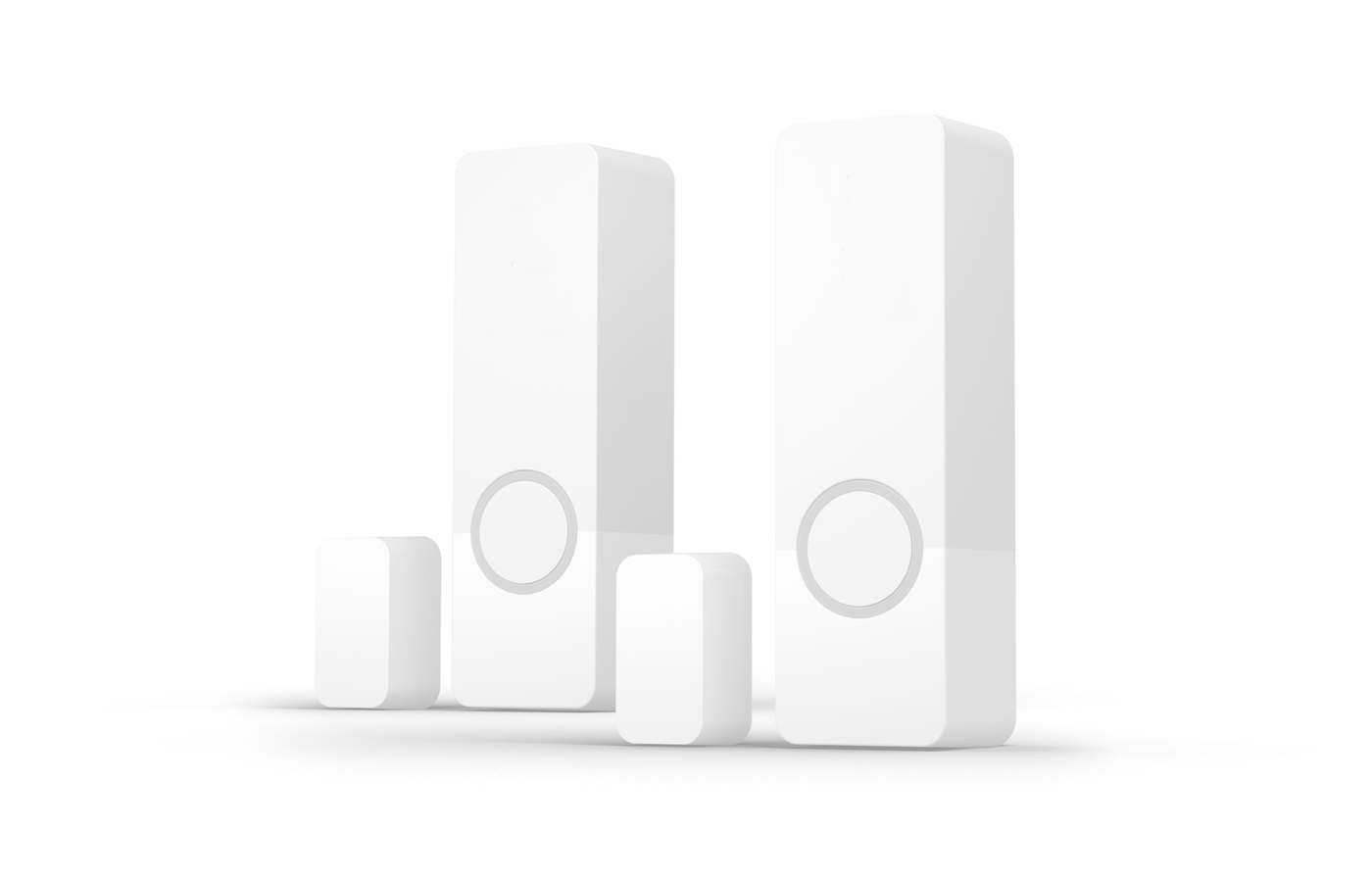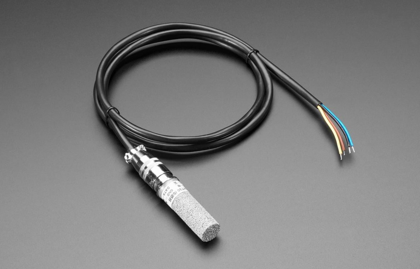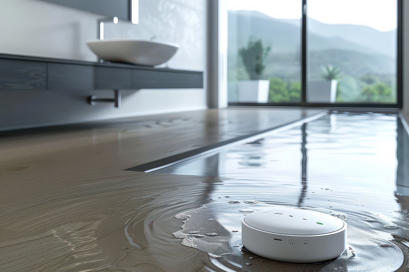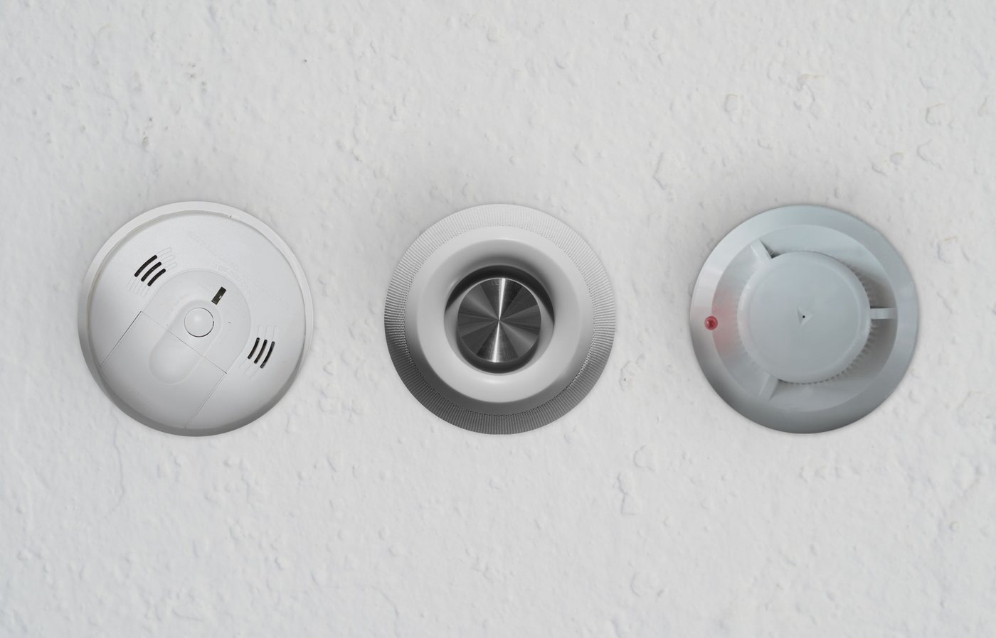
Solution - Smoke and Fire Sensors
Description
Connection
- Follow the wiring guidelines of the specific smoke sensor.
- The sensor is connected to the controller I/O terminals via its own relay contact, so the detection signal reaches the system reliably.
- The sensor is configured in the PIERRE Partner application, and then appears for the client in the Smart PIERRE application.
What It Can Trigger
- Notifications by message or call, so occupants are alerted.
- Activation of external sirens.
- Switching off electrical circuits in the building.
- Combined responses together with alarms and other system functions.
Important Notice
The PIERRE system is a building automation and smart home control system. It is not a certified fire alarm or life-safety system. It can monitor sensors, generate events and send notifications, but it must not be considered a replacement for a certified fire detection system where one is required by local regulations, insurance requirements or project specifications.
Technical Notes
- Where a certified smoke detector is required, install the certified device and use the system for the additional automation on top of it.
- Mount detectors at ceiling level, away from ventilation outlets, and follow the spacing given in the local regulation.
- Smoke detectors have a stated service life and replacement interval. Note the installation date and agree the replacement schedule with the customer.
- Test each detector at handover with the manufacturer's test method, and confirm both the notification and the automated actions.
Schemes
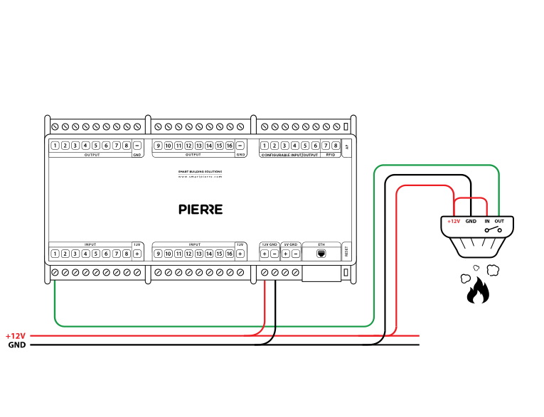
Wiring PIERRE Smoke sensor - Electric schemes
Cables
| Position | Wires | Diameter | Type | Comment |
|---|---|---|---|---|
| From Smoke sensor to PIERRE | 3 | cat.5 | UTP | +12V, GND, SIGNAL |
Troubleshooting
Green – Online: the controller is connected to the network and operating normally. Red – Offline: the controller is disconnected from the network, or there is no internet access. White – Commissioning: the controller has started in commissioning mode and is waiting to be commissioned. Light blue – AP mode: the controller is broadcasting its own network for setup or configuration. Dark blue – Selected in the app: the controller is currently selected in the PIERRE Partner app, which helps you identify the physical controller in the cabinet. Purple – Searching for IP address: the controller is waiting to receive an IP address from the router. Orange – Firmware update: a firmware update is in progress; do not power off the controller while the LED is orange.
If not, add it in the PIERRE Partner app.
If not: Give it a try. If the sensor has been newly added, it needs a state change.
If not, wire it as shown in the diagram. To rule out the detector and its cable, briefly bridge the controller's 12 V output to the input the detector is wired to. If the input turns green in the app, the controller and the input are fine and the fault is in the detector or its cable.
When an input triggers an output — for example a motion sensor that switches a lamp — add both to the same controller. This gives the fastest response.
No. PIERRE smoke and gas sensors are not certified fire-alarm components. They are intended for early warning and automation (notifications, switching off appliances) and do not replace a certified fire-alarm system where one is required.
Each sensor (motion, light, contact, etc.) is wired individually to the PIERRE distribution cabinet in a star topology. • INPUT 12–24 V – 12 V DC from the PIERRE controller • GND – GND from the PIERRE controller • Switch K1 – to INPUT 12–24 V • Switch K2 – to a digital input of the PIERRE controller