Solution - Humidity and Temperature Sensors
Description
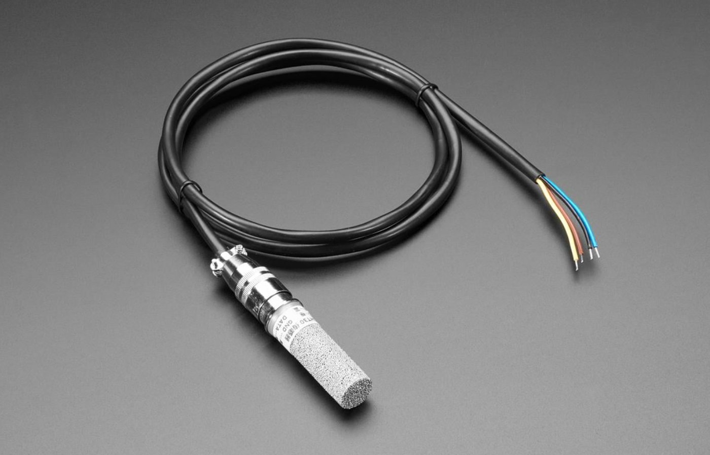
The combined humidity and temperature sensor measures both the temperature and relative humidity of a room with a single device. The measured values are transmitted to the PIERRE Controller, where they can be displayed in the PIERRE system and used as conditions for heating, cooling, ventilation, and other automations.
Two types are available for use with the PIERRE system:
-
SHT30
-
SHT30 Modbus
Connection
Sensor wiring must be routed separately from mains (230 V) wiring to avoid potential communication interference and measurement errors.
SHT30
-
Cat.6 SFTP cable is recommended for connecting the sensor to the PIERRE Controller.
-
For cable runs exceeding 10 metres, a differential module is required at the sensor end to ensure stable and reliable communication.
SHT30 Modbus
-
A TTL converter is required to connect SHT30 Modbus sensors to the PIERRE system.
-
A cable with a minimum cross-section of 4 × 0.5 mm² is recommended between the sensor and the TTL converter.
-
When multiple sensors are used, the wiring can be implemented in a bus (daisy-chain) and/or star topology.
Configuration – SHT30
-
Open the desired Controller in the PIERRE Partner application.
-
Navigate to Configurable I/O and select the appropriate humidity and temperature sensor.
-
Select the Pin (1–6) to which the sensor is physically connected on the Controller.
-
Configure the required parameters:
-
Name – Enter a name for the sensor.
-
Role – Select the appropriate role.
-
Image – Select an image for the sensor.
-
-
Save the configuration.
Configuration – SHT30 Modbus
The SHT30 Modbus sensor configuration consists of two steps: first, the Modbus RTU communication must be configured, and then the sensor must be added.
1. Create the Modbus RTU Connection
Open the desired Controller in the PIERRE Partner application.
-
Navigate to Configurable I/O and select Modbus RTU.
-
Configure the following parameters:
-
Name – Enter a name for the connection, for example: Humidity-Temperature Modbus.
-
Role – Select the appropriate role.
-
TX – Select the Configurable I/O Pin (1–6) to which the TX terminal of the TTL converter is physically connected.
-
RX – Select the Configurable I/O Pin (1–8) to which the RX terminal of the TTL converter is physically connected.
-
Baud –
9600 -
Parity –
None -
Stop Bits –
1
-
-
Select Add to create the Modbus RTU connection.
2. Add the SHT30 Modbus Sensor
Once the Modbus RTU connection has been created, add the sensor under Devices:
-
Select Add New Modbus I/O.
-
Select Humidity and Temperature Sensor as the device type.
-
Name – Enter a name for the sensor.
-
Address – Enter the Modbus address of the sensor. For example, the first device can use address
1. When multiple sensors are connected, each device must have a unique address, such as1,2,3,4, etc. -
Save the configuration.
Technical Notes
-
For the SHT30, the required cable length must be considered during the planning stage. For cable runs exceeding 10 metres, a differential module is required.
-
It is recommended to connect a maximum of 20pcs SHT30 Modbus sensors to one network.
-
Install the sensor in a location where it can measure representative room temperature and humidity. Avoid locations exposed to direct sunlight, strong airflow, heat sources, or direct water spray.
-
After installation, allow the sensor sufficient time to adapt to the room conditions before evaluating the measured values.
-
If the sensor consistently measures higher or lower values compared to a reference measurement, the reading can be corrected using the Offset setting.
Schemes - SHT30
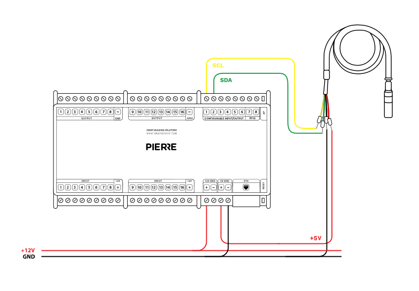
Wiring of SHT 30 Combinated Humidity and Temperature sensor/take care to use SFTP cable and the length should not exceed 5 meters. - Electric schemes
Cables - SHT30
| Position | Wires | Diameter | Type | Comment |
|---|---|---|---|---|
| From PIERRE to SHT30 | 4 | cat.6 | SFTP | +5V, GND, SCL, SDA |
Schemes - SHT30 modbus
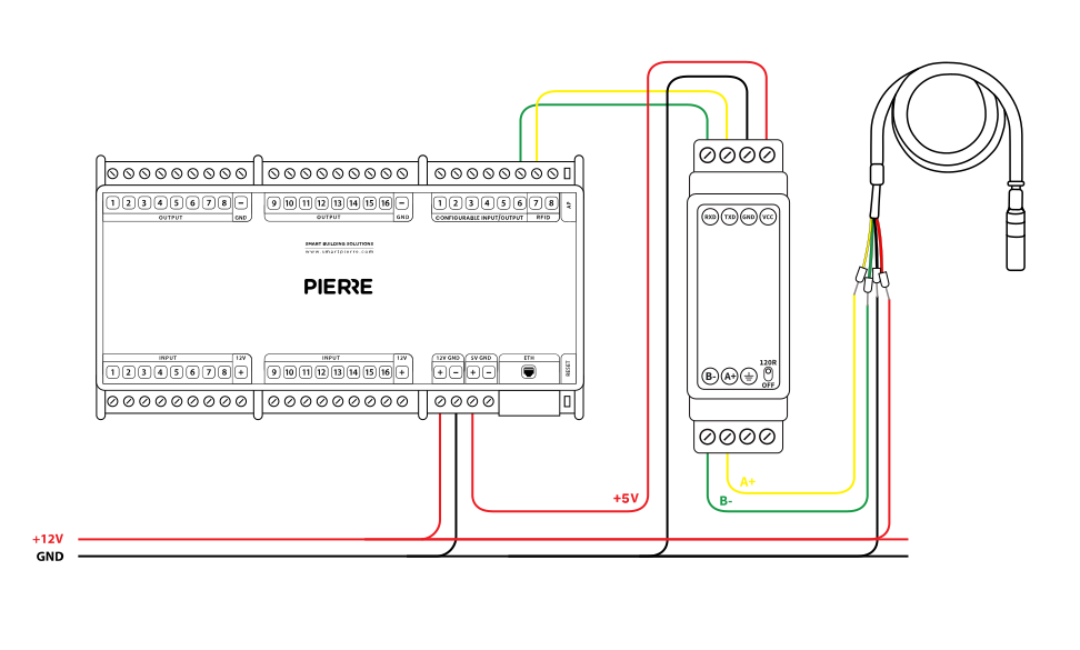
Wiring of compatible combinated Humidity and Temperature sensor - Electric schemes
Cables - SHT30 modbus
| Position | Wires | Diameter | Type | Comment |
|---|---|---|---|---|
| From PIERRE to TTL modul | 4 | 0.75 mm² | H07V-K | +5V, GND, RX, TX |
| From PIERRE to SHT30 modbus | 4 | 0.75 mm² | H07V-K | +12V, GND, A+, B- |
Troubleshooting
Green – Online: the controller is connected to the network and operating normally. Red – Offline: the controller is disconnected from the network, or there is no internet access. White – Commissioning: the controller has started in commissioning mode and is waiting to be commissioned. Light blue – AP mode: the controller is broadcasting its own network for setup or configuration. Dark blue – Selected in the app: the controller is currently selected in the PIERRE Partner app, which helps you identify the physical controller in the cabinet. Purple – Searching for IP address: the controller is waiting to receive an IP address from the router. Orange – Firmware update: a firmware update is in progress; do not power off the controller while the LED is orange.
If not, add it in the PIERRE Partner app.
Check the polarity first: a reversed supply damages the sensor (it must be +5 V). If the wiring is right and the sensor still gives no reading, try swapping SDA and SCL.
When an input triggers an output — for example a motion sensor that switches a lamp — add both to the same controller. This gives the fastest response.
Yes. Join the sensor cable to a UTP or shielded (F/UTP or S/FTP) cable with quick connectors (e.g. Wago) or by soldering. Keep the total length short: the sensor uses the I²C bus, which is not designed for long cable runs.
The sensor is wired individually to the PIERRE controller with four wires: GND, +5 V, SDA and SCL (I²C). Use a shielded cable, keep the run as short as possible and never reverse the polarity — a reversed +5 V destroys the sensor.